Download
1 / 24
240 likes | 245 Views
aLIGO Monolithic stage. Giles Hammond, University of Glasgow for the Advanced LIGO Suspensions Team. aLIGO/aVirgo Workshop Pisa, Italy 23 rd -24 th February 2012. LIGO-G1200109-v1. Overview. Overview of the Monolithic suspension design for Advanced LIGO

E N D
aLIGO Monolithic stage Giles Hammond, University of Glasgow for the Advanced LIGO Suspensions Team aLIGO/aVirgo Workshop Pisa, Italy 23rd-24th February 2012 LIGO-G1200109-v1
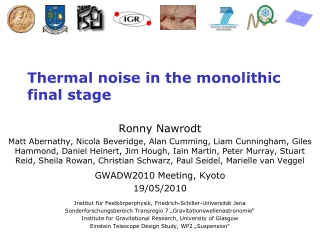
Overview • Overview of the Monolithic suspension design for Advanced LIGO • Monolithic suspension fabrication (LIGO Hanford) • Bend points and modal frequencies • Thermal noise of the upper stages (Mathematica code) • Thermal noise of the final stage (Finite Element Modelling) • Comparison of FEA with measured violin modes • Summary
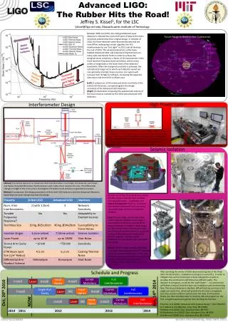
aLIGO Quadruple Suspension • Seismic isolation: use quadruple pendulum with 3 stages of maraging steel blades for horizontal/vertical isolation • Thermal noise reduction: monolithic fused silica suspension as final stage • Control noise minimisation: use quiet reaction pendulum for global control of test mass position • Actuation: Coil/magnet actuation at top 3 stages, electrostatic drive at test mass four stages 40kg silica test mass parallel reaction chain for control
Steel wires Penultimate mass Ear Ear Steel wire break-off prism Silica fibres Weld Stock Neck Fibre End/input test mass Ear aLIGO Monolithic Stage Horn
Monolithic Suspension at LIGO Hanford • Hydroxide catalysis bonding of the ears • Fibre pulling with CO2 laser • Fibre profiling for importing into Finite Element Analysis A. Cumming et al, Rev Sci Inst 82, 044502 (2011)A. Heptonstall et al, Rev Sci Inst 82, 011301 (2011)
Monolithic Suspension at LIGO Hanford • PUM and ITMy installation with ERGO arm • Alignment was performed with: • autocollimator • scale/auto leveller • Perform 8 welds to PUM and ITMy • De-stress welds (to set pitch angle) • Hang
Modal frequencies • The modal frequencies of interest are: • For the test mass • Pendulum (longitudinal and transverse) • Pitch • Yaw • Roll • Bounce or vertical • For the fibres • Violin mode(s) of each fibre Autocollimator Optical lever Shadow sensor (violin modes)
Overview of the Modal Frequencies * with the PUM free, this will correspond to a lowest vertical suspension mode frequency of approximately 9.2 Hz AC: Auto Collimator OL: Optical Lever
Violin Modes • FEA predicted frequency of 1st violin mode is 511Hz • Measured spread of 512Hz±3Hz (=> uniform fibre dimension and fibre tension)
Analysis of Bend Points • Prior to welding each fibre is profiled using a camera and edge finding software to produce a cross-sectional profile along its length • Transferred to ANSYS to determine how the fibre bends under loading • The bend point is set through fibre profiling and knowledge of material consumed during welding CoM 10.8mm Effective bending point • The region where bending takes place is designed to be close to 800m diameter to reduce thermoelastic noise • d=10±1mm gives: fpendulum=0.653±0.002Hz • fpitch =1.07±0.02Hz Attachment point Effective bend point CoM
Thermal Noise Modeling • Upper stages: • Mathematica based model (M. Barton, T020205-02, http://www.ligo.caltech.edu/~e2e/ • SUSmodels/). • rigid bodies with up to 6 DoF • wires with longitudinal/transverse/torsional elasticity • springs described by a 6x6 matrix of elastic constants • arbitrary damping function (e.g. structural, viscous) • thermal noise/transfer function estimate • Monolithic stage: • ANSYS Finite Element Analysis. • realistic fibre geometries and dilution • fibre, weld, horn and bond loss included • pendulum and vertical thermal noise estimate • violin mode loss (Q) and thermal noise estimate • thermal noise due to laser beam Lower stage Upper stages
Mathematica Model and the PPP Model • The Mathematica model describes the same physics as the modelling tools for the VIRGO pendulum (PPP effect) • A simple model of the VIRGO+ suspension was used to predict the thermal noise performance (m1=101kg, m2=61kg, m3=20kg). Viscous damping and thermoelastic loss were added to the Marionetta and reaction mass. The silica stage included thermoelastic and surface loss. • Results identical within factor of 2 Mathematica VIR-0015E-09
Mathematica Model and the PPP Model Mathematica VIR-0639E-09
A. Cumming - "Aspects of mirrors and suspensions for advanced gravitational wave detectors“, PhD thesis, Glasgow, 2008. R. Kumar - "Finite element analysis of suspension elements for gravitational wave detectors“, PhD thesis, Glasgow, 2008. Dissipation Dilution from FEA • Use ANSYS to predict dilution of real fibre geometries • A variety of different geometries were analysed including fibres/ribbons, 2-wire and 4-wire (GEO/aLIGO) pendulums with/without necks. m
Dissipation Dilution from FEA • ANSYS used to predict energy stored in the suspension elements (elastic and kinetic) • Model accepts real fibre data from profiler in order to calculate accurate dilution values A. Cumming et al., Class. Quantum Grav., 215012, 2009 • aLIGO pendulum dilution 91 (energy in fibre necks is important for realistic estimation)
M. Barton et al, T080091, 2008 A. Gretarsson and G.M. Harry, Rev. Sci. Instrum., 70, 4081–7, 1999 S.D. Penn et al., Phys. Lett. A, 352, 3–6, 2006 G. Cagnoli and P. Willems, Phys. Rev. B, 65, 174111, 2002 A. Cumming et al, Class. Quantum Grav., 26, 215012, 2009 Final Stage Thermal Noise Model • Use the following loss terms to model the bond, weld region and silica fibres • The FEA model calculates the energy stored in each section of the lower silica stage which results in (where the sum extends over the bonds, horns, welds and fibre). • The total loss (undiluted) is given by: • the thermoelastic time constant () is modified depending on whether fibres or horns are modelled
Energy Stored in the Fibre • It is important to model all sources of loss (e.g. fibre, weld, horn and bond) • For the aLIGO pendulum mode 91.5% of energy in the fibre, 6.3% of energy in the weld, remainder in horns • For aLIGO violin modes, more energy stored in neck/horn/weld as frequency increases => violin mode Q decreases with higher frequency fibre 400m fibre horn horn Weld regions
Energy Stored in the Fibre • ANSYS was used to predict energy ratio in different parts of the lower stage • The largest energy ratio is in the fibre. The majority of the energy ideally resides in the 800m thermoelastic cancellation region • Although the bond has high loss, there is very little energy stored in that region and thus the effect on the diluted loss is 1%
Overview of Thermal Noise Terms P. Willems et al., Physics Letters A 319 (2003) 8–12
Bond Thermal Noise due to Laser Beam • The previous treatment of bond thermal noise determines the loss associated with energy stored due in the pendulum mode (i.e. treating it as part of the fibre) • The loss associated with thermal noise from the Gaussian laser beam is also included using the model of Levin • The strain energy, , in the material is evaluated at each node of the FE model and summed to find Wdiss • The total thermal noise is then
aLIGO Final Stage Displacement Noise • thermal displacement noise for single test mass A. Cumming, Class. Quantum Grav. 29 (2012) 035003
Violin Mode Quality Factors (LASTI) • 1st/2nd violin modes (n=1, n=2) measured on LASTI monolithic.
aLIGO Violin Modes (LASTI) • The measured and modelled frequencies tie up well indicating a good accuracy of model geometry compared to the real suspension • For V1 the projected Q from FEA is to within 7% of measured value • For V2 the projected Q from FEA is to within 19% of measured value • As frequency increases the dilution reduces due to more energy in horn/weld/fibre neck • Surface loss and weld loss have roughly equal contributions => important to model
Summary • aLIGO Monolithic suspensions now installed at LASTI, MIT and 2x LIGO Hanford • The suspension is well engineered and a robust procedure is in place to both build and repair (LIGO Hanford suspensions performed by LIGO personnel) • A range of tools have been developed to model the suspension performance (Mathematica and ANSYS). Mathematica model has been used to predict VIRGO+ sensitivity within a factor of 2. • The use of real fibre geometries are necessary for accurate dilution/mechanical loss/thermal noise estimates • There is good agreement between measured/predicted modal frequencies and bending points • The measured violin modes at LASTI show high values (Q=611M for n=1 and Q=462 for n=2)which agree well with FEA • Accurate thermal noise estimates and violin mode Q’s require accurate estimation of all energy loss processes (i.e. loss in weld, horn, bond)