Download
1 / 14
140 likes | 142 Views
This text explains the concept of induced electromotive force (EMF) and Faraday's Law of Electromagnetic Induction. It discusses the calculation of magnetic flux, direction of induced current, Lenz's Law, and the application of these concepts in transformers.

E N D
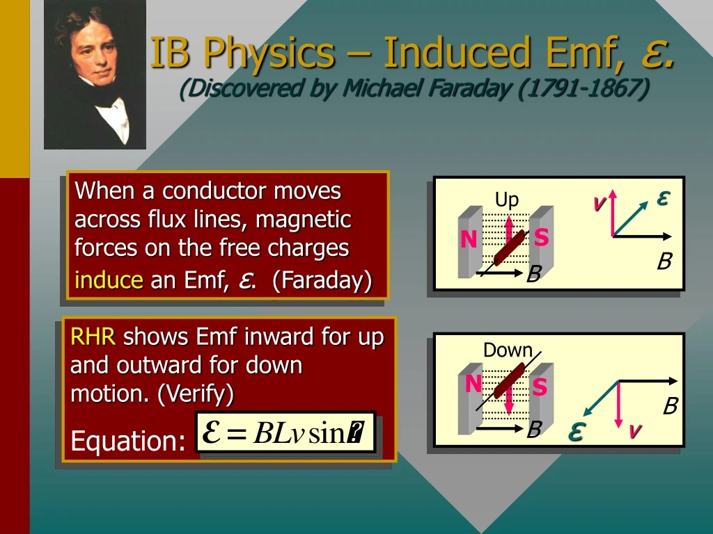
B B Down ε Up v B B ε v IB Physics – Induced Emf, ε.(Discovered by Michael Faraday (1791-1867) When a conductor moves across flux lines, magnetic forces on the free charges induce an Emf, ε. (Faraday) S N RHR shows Emf inward for up and outward for down motion. (Verify) Equation: N S
Df Magnetic Flux is greatest at the B poles. Φ = BA A Magnetic Flux[from Wilhelm Weber (1804-1891)] • Magnetic flux lines Fare continuous and closed. • Direction is that of the B vector at any point. Flux – (Weber, Wb) maximum when area A is normal to the magnetic field. Magnetic Field strength (flux density) can be measured as the Wb/m2 , since B = Φ/A.
n A q B Calculating Flux When Area is Not Perpendicular to Field The flux penetrating the area A when the normal vector n makes an angle of q with the B-field is: q is the angle that the normal to the plane of the area makes with B field.
B Faraday’s observations: Flux lines F in Wb N turns; velocityv Faraday’s Law: Induced EMF: Observations • Relative motion induces emf. • Direction of emf depends on direction of motion. • Emf is proportional to rate at which flux lines are cut (v). • Emfis proportional to the number of turns N. The negative sign means that E opposes its cause.
x x x x x x x x x x x x x x x x n n n q A (c)q = 600 A = .004m2 (a)q = 00 (b)q = 900 Example 1: A current loop has an area of .004 m2and is placed in a 3-T B-field at the given angles. Find the fluxF through the loop in each case. (a)F = BA cos 00 = (3 T)(0.004 m2)(1); F = 12.0 mWb (b)F = BA cos 900 = (3 T)(0.004 m2)(0); F = 0 mWb (c)F = BA cos 600 = (3 T)(0.004 m2)(0.5); F = 6.00 mWb
A change in flux DF can occur by changing: the area, the B-field, or the angle. Faraday’s Law: n n n Rotating loop = B DA Loop at rest = A DB Application of Faraday’s Law
N = 200 turns n q N S B B = 4 mT; 00 to 900 Example 2: A coil has 200 turns of area 30 cm2. It flips from vertical to horizontal position in a time of 0.03 s. What is the induced emf if the constant B-field is 4 mT? DA = 30 cm2 – 0 = 30 cm2 DF = B DA = (4 mT)(30 cm2) DF = (0.004 T)(0.0030 m2) DF = 1.2 x 10⁻⁵ Wb E = -0.080 V The negative sign indicates the polarity of the voltage.
Induced B Induced B Left motion I Right motion N S N S I Lenz’s Law[from H.F.E. Lenz (1804-1865)] Lenz’s Law: An induced current will be in such a direction as to produce a magnetic field that will oppose the motion of the magnetic field that is producing it. Flux increasing to left induces loop flux to the right. Flux decreasing by right move induces loop flux to the left.
R Example 3: Use Lenz’s Law to determine direction of induced current through R if switch is closed for circuit below (B increasing). Close switch. Then what is direction of induced current? The rising current in right circuit causes flux to increase to the left, inducing current in left circuit that must produce a rightward field to oppose motion. Hence current I through resistor R is to the right as shown.
I B x x x x x x x x x x x x x x x x x x x x x x x x x x x x x x x x x x x x x x x x x x x x x x x x x x x x x x x x x x x x I v v v x x x x x x x x x x x x x x x x x x I v x B Induced emf Lenz’s law Directions of Forces and EMFs I An emf E is induced by moving wire at velocity v in constant B field. Note direction of I. L From Lenz’s law, we see that a reverse field (out) is created. This field causes a leftward force on the wire that offers resistance to the motion. Use right-hand force rule to show this.
E x x x x x x x x x x x x x x x x x x x x x x x x x x x x x x x x x x x x x x x x x x x x x x B I I L v v B q v sin q v x Induced Emf E Motional EMF in a Wire Force F on chargeqin wire: F = qvB; Work = FL = qvBL EMF: If wire of length L moves with velocity v an angle q with B:
North v q B South North v I B South Example 4:A 0.20-m length of wire moves at a constant speed of 5 m/s in at 1400 with a 0.4-T B-Field. What is the magnitude and direction of the induced emf in the wire? E = -0.257 V Using right-hand rule, point fingers to right, thumb along velocity, and hand pushes in direction of induced emf—to the north in the diagram.
The Transformer[co-discovered in 1831 by Michael Faraday (1791-1867, England) and Joseph Henry (1797-1878, USA)]