Download
1 / 13
130 likes | 218 Views
Yongguang Liang. Detailed Design of Shield House and Collimators wrt Backgrounds. Shield wall and entrance window design Strategy for detailed design of collimator: 2 bounce system Summary. Just getting started – will probably take months to finalize!. Possible Backgrounds Include.

E N D
Yongguang Liang Detailed Design of Shield House and Collimators wrt Backgrounds • Shield wall and entrance window design • Strategy for detailed design of collimator: 2 bounce system • Summary Just getting started – will probably take months to finalize!
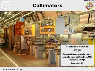
Possible Backgrounds Include • background from target windows, beam pipe, • collimators, … • background from secondary reactions (Compton scattering • Bremsstrahlung process, multiple scattering, …) • background from inelastic reactions and Moller scattering • Only ep-elastic scattering in target and consider secondaries
Shield Wall and Window Design Goal: Minimize soft backgrounds near region III chamber while not introduce noise or dilution from showers Consider: 1.Location, material, and thickness of the shielding wall location of main torus and region III chamber Z=330-430 cm 10 radiation lengthsnormal shielding concrete least 1.0 m thick MAX space ~ 70 cm 2. Shape and size of shielding entrance window Found we must address more basic issues (such as the source of the upstream background, design of a “two bounce system”) before we can design a suitable entrance window.
Comparison of 0.5 m Wall to 1.0 m Wall case 0.5m wall 1.0 m wall Red: charged particles (mostly e-) Blue: neutral particles (mostly photon)
Source of Photon Background that hits the Quartz and Deposits > 5 MeV Energy Primary collimator x vs z y vs z X vs Z
Photon Background (continued) Significant amount of g background from shower leakage at primary collimator Eg > 5 MeV signal at Quartz. Based on VPI “final” primary collimator g background ~0.08% But these studies: only ep elastic in target in the first octant Consider eight octants and inelastic reactions get larger AND difficult to measure Reduce this background with “Two Bounce System” ie quartz NO direct line of sight to g source
View of Spectrometer from the Quartz Looking upstream from Quart location along the central scattered electron trajectory: we see * inner lips of the primary collimator opening (yellow) Qweak spectrometer is a “one bounce” system. Modified to “two bounce” system in later slide
Another view of the Spectrometer Looking upstream from left edge of quartz to the spectrometer: See *adjacent octant opening, *minitorus(violet), *upstream cleanup collimator (green).
Demonstration of “Lintel Collimator” 60 cm downstream of Downstream Cleanup Collimator Looking upstream from Quart location along the central scattered electron trajectory with * “lintel collimator” * primary collimator thickness 21.66 cm 5.25 cm Defining collimator barely seen
From Left Edge of Quartz with “Lintel Collimator” 60 cm downstream of Downstream Cleanup Collimator
Elastic Collimator Detailed Design Strategy Reduce g background from the defining collimator two bounce system 1. Change primary collimator from Lead to Tungsten (W- Cu) Reduces the background from 0.08% to 0.04% 2. Cost management: reduce primary collimator thickness 21.66 cm 5.25 cm AND this 15 radiation lengths is sufficient 3. Cantilever a lintel from downstream collimator to block line of light between quartz and defining collimator 4. Move defining collimator slightly upstream if necessary (?) 5. Optimize primary collimator tilt angles (both x and y directions) 6. Finalize upstream cleanup and beam-defining collimation Iterate with region I, II, III folks, VPI acceptance folks, and Neven to make sure we DON'T break anything. Finally, Neven's background simulation needs to be repeated with the final collimator configuration.
Summary * We are just getting started on the detailed collimator design with respect to backgrounds using the outlined strategy * General shape of elastic e envelope will not change * Work in Progess!