Download
1 / 21
210 likes | 338 Views
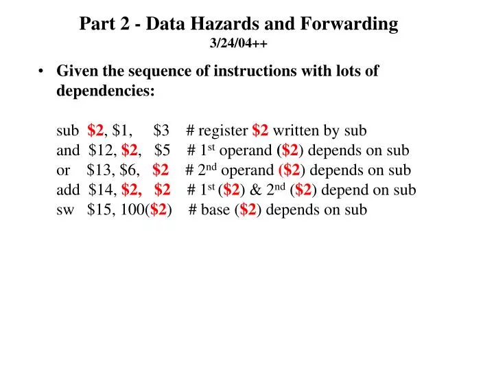
Part 2 - Data Hazards and Forwarding 3/24/04++.

E N D
Part 2 - Data Hazards and Forwarding3/24/04++ • Given the sequence of instructions with lots of dependencies:sub $2, $1, $3 # register $2 written by suband $12, $2, $5 # 1st operand ($2) depends on subor $13, $6, $2 # 2nd operand ($2) depends on subadd $14, $2, $2 # 1st ($2) & 2nd ($2) depend on subsw $15, 100($2) # base ($2) depends on sub
Data Hazards and Forwarding (cont.) Fig. 6.36
Data Hazards and Forwarding - Concepts • Problem page 477 Basic reference figure: fig. 6.30, p. 470 • Where to start looking for the hazard (for example on p. 477) • For a given “receiving” (reading) instruction,Look in the EX phase where the ALU needs the data. • Next, using fig. 6.36: During this execution phase clock cycle for the reading instruction, “go vertically up” to the “sender” (writer) and see where the writer is during this same clock cycle. If the writer is not after (ie., before) the WB phase (MEM/WB), then there is a hazard. • Data hazard detection • Assume that all register number fields (5 bits each) are propagated from IF/ID to ID/EX – rs path must be added rd & rt already there (take early look at fig 6.40). • Notation (example):ID/EX.RegisterRs refers to the identification (5 bit field – one of 32) of the rs register whose 5 bit “name” or identification is found in the pipeline register ID/EX. • Use similar notation for other pipeline registers and rt and rd.
Data Hazards Detection – Concepts • How to write down conditions for a hazard - which represents the logic for detection of a potential hazard. • Case 1: read immediately after a write for a common register. • Check the EX phase(ALU input) of read:We need ID/EX.RegisterRs in the same clock pulse as that of the destination register in the register file being written. • Check what register is actually being written:In the example it is EX/MEM.RegisterRd (due to sub instruction).If the latter register is not the register file itself or after, then we have a data hazard. • In this case we have the following simple test for a data hazard:EX/MEM.RegisterRd = ID/EX.RegisterRs==> hazardIn book, see 1a and 1b for two possibilities
Data Hazards Detection – Concepts (cont.) • Case 2: read after a write after 1 clock pulse for a common register. • Check EX phase(ALU input) of read:We need ID/EX.RegisterRs in the same clock pulse (or later) as that of the destination register in the register filebeing written. • Check what register is actually being written:In the example it is EX/WB.RegisterRd (due to sub instruction).If the latter register is not the register file itself or after, then we have a data hazard. • In this case we have the following simple test for a data hazard:MEM/WB.RegisterRd = ID/EX.RegisterRs ==> hazardIn book, see 2a and 2b for two possibilities • General Rule:See what “write” register is being written by a previous instruction at the same clock pulse as the “read” instruction ==> check to see if this “write” register is the register file or after. If not we have a hazard. • Or, more concisely, use the logical hazard tests referred to aboveSee next:
The Essence of a Data Hazard So Far • Necessary & sufficient conditions for data hazards in example: “writer” “reader”1a. EX/MEM.RegisterRd = ID/EX.RegisterRs1b. EX/MEM.RegisterRd = ID/EX.RegisterRt2a.MEM/WB.RegisterRd = ID/EX.RegisterRs2b. MEM/WB.RegisterRd = ID/EX.RegisterRt • When one of the above conditions hold, we may assert a control line which would do the appropriate forwarding – when and onlywhen a test is valid. • Conditions will be expanded on later. • Happily not only can we detect a hazard, but we can fix it for this case with no stalls because, although the data is not in the register file, it does exist in EX/MEM for a “type 1” hazard, and in MEM/WB for “type 2” hazard. Unhappily, there will be a case (lw writes) where a stall is needed – see later. • Example: “and $12, $2, $5” reads $2 during same clock cycle as “sub $2, $1, $3” sets the EX/MEM pipeline register. But the “and” instruction requires the register file to be updated during this cycle in order to get the correct data. This won’t happen until two clock pulses in the future – hence a data hazard of type 1a.
Forwarding • Forwarding: release the information to the EX phase of next instruction early (if possible), rather than waiting to store it in the register file. • Extra conditions for forwarding: • Source or “writing” instruction actually writes ==> EX/MEM.RegisterRd is true – this is the RegWrite control line to the register file. • Target register being written is not $0==> EX/MEM.RegisterRd 0maybe $0 is used by assembler generated dummy instructions such assll $0,$1,2 which could possibly forward a non-zero value for $0The receiving instruction won’t need forwarding if it is reading $0, since $0 is hardwired to 0. • Two new control lines for MUX feeding ALUForwardA, 2 bitsForwardB, 2 bitsThese lines can select • Normal data from ID/EX (00) • Data forwarded from MEM/WB (01) • Data forwarded from EX/MEM (10) • See fig. 6.37, p. 481 for forwarding resolution • See fig. 6.38, p. 482 for forwarding controls
Forwarding Resolution Fig. 6.37
Forwarding Details • Conditions for setting these forwarding control lines.Type 1 hazard – reading source register set by preceding instruction: • EX hazard (1a)if {EX/MEM.RegWrite // register file is actually being writtenand (EX/MEM.RegisterRd 0) //avoid forwarding $0and (EX/MEM.RegisterRd = ID/EX.RegisterRs)} // conditions for a hazard then ForwardA = 10 // use EX/MEM • EX hazard (1b)if {EX/MEM.RegWrite // register file is actually being written and (EX/MEM.RegisterRd 0) //avoid forwarding $0 and (EX/MEM.RegisterRd = ID/EX.RegisterRt)} // conditions for a hazard then ForwardB = 10 // use EX/MEM
Forwarding Details (cont) • Conditions for setting these forwarding control lines.Type 2 hazard – reading source register set two instructions ago: • MEM hazard (2a) // register file is actually being written if {MEM/WB.RegWrite and (MEM/WB.RegisterRd 0) //avoid forwarding $0 and (MEM/WB.RegisterRd = ID/EX.RegisterRs)} // conditions for a hazard then ForwardA = 01 // use MEM/WB • MEM hazard (2b) // register file is actually being written if {MEM/WB.RegWrite and (MEM/WB.RegisterRd 0) //avoid forwarding $0 and (MEM/WB.RegisterRd = ID/EX.RegisterRt)} // conditions for a hazard then ForwardB = 01 // use MEM/WB • In general, if the previous instruction is going to write the register file, and the write register number matches the read register number of ALU inputs A or B, provided it is not register 0, the steer the MUX to pick up the value from pipeline register EX/MEM (using the new ForwardA or ForwardB MUX lines). • See Fig 6.38 for role of forwarding unit
Forwarding Unit Before Fig 6.38 After How did rs get here? See fig 6.39 for details on ALU MUX operation
Forwarding Unit Selector values 00 01 10 How rs got there Fig 6.40
Forwarding –Further Complications for type 2 (p. 483) • Example:add $1, $1, $2add $1, $1, $3add $1, $1, $4… • The 3rd instruction has both a “type 1” and a “type 2” hazard for the same register $1. The preceding hardware haas a conflict as what to forward. • There is a forwarding condition from both the WB stage and the MEM stage, Resolution: choose the MEM stage data because it would be the most recent result. • Use this logic for type 2 only if there is not also a type 1 hazard, else use the type 1 logic – gives most recent value: • MEM hazard (2a)if {MEM/WB.RegWrite and (MEM/WB.RegisterRd 0) //avoid forwarding $0and (EX/MEM.RegisterRd ID/EX.RegisterRsand (MEM/WB.RegisterRd = ID/EX.RegisterRs)} // conditions for a hazard then ForwardA = 01 – use MEM/WB • MEM hazard (2b)if {MEM/WB.RegWrite and (MEM/WB.RegisterRd 0) //avoid forwarding $0 and (EX/MEM.RegisterRd ID/EX.RegisterRtand (MEM/WB.RegisterRd = ID/EX.RegisterRt)} // conditions for a hazard then ForwardB = 01 – use MEM/WB
Forwarding – scenario • An example illustrating the forwarding design to this point:sub $2, $1, $3and $4, $2, $5 # type 1 hazardor $4, $4, $2 # type1 and type 2 hazard on different registersadd $9, $4, $2 # type 1 and type 2 hazard on same register • See fig. 6.41 – 6.42 (see pdf’s).
Forwarding –The Plot ThickensStill Further Complications • To now, data hazards were associated with using a source register in an instruction which was after register type instruction just modified it. • We were able to resolve the hazard by “finding” the needed data early in a pipeline register, and thus did not have to wait (stall)for it to “percolate” to the register file. • The “early” data was then fed to the ALU inputs for the instruction needing it. • If we did not do this forwarding we would have to stall the instructions following the “writing” instruction in order to wait for the data to get to the register file. • Unfortunately, if we replaced the “register type” writing instruction by the load word (lw) memory instruction, the timing won’t work out – we need an extra cycle to read memory to get the desired data and it won’t be available in an early pipeline register in time for the EX phase of instructions which follow. • The “register writing” instruction short circuited the memory access and was available early in a pipeline register (what we saw to this point). • Not so with lw
Still Further Complications Hazards using lw EX/MEM (MEM/WB) Must first read memory to get data $2 $2 $2 $4 Fig. 6.44 Can forward only to the “or” and “add” instructions without stalling $2 still unavailable in EX/MEM for “and”. When sub was the “writing” instruction, we forwarded from EX/MEM to the ALU for “and”
Solution to “lw” Hazard Problem • Detect this situation using a “Hazard Detection Unit” as opposed to the previous “Forwarding Unit”. • When this situation is detected, instructions which follow are stalled for a clock cycle in order to give the data time to be forwarded. But the lw will be allowed to proceed. • The logic for detection is:if ( (ID/EX.MemRead = 1) and// test control line for an lw instruction((ID/EX.RegisterRt = IF/ID.RegisterRs) or //LHS=destination for lw, RHS= an operand for following “and” inst (ID/EX.RegisterRt = IF/ID.RegisterRt )))//LHS=destination for lw, RHS= an operand for following “and” instthen stall the pipeline one cycle. • Compare these equations with those for “normal” type 1 and type 2 hazard forwarding.
Now that we detected the “lw Hazard Problem”,How Do We Stall • Since we are detecting this in the ID stage while the lw is in the EX phase, we must “freeze” the two instructions that follow in the IF and ID stages for one cycle, but allow the lw to proceed. • This is accomplished by preventing the PC and IF/ID register from changing. • New control lines from hazard detection unit neededPCWrite – allows PC to be written only when asserted IF/IDWrite - allows IF/ID pipeline register to be written only when asserted • When these lines are de-asserted the instructions in the IF and ID stages will stay “as is” for one clock cycle – a freeze. • Because the lw is allowed to advance to MEM stage, we must guarantee that the EX stage becomes “benign” – since no instruction is entering it – we insert a “bubble”, or effectively insert a “nop” there. • This is accomplished by forcing all zeros in the EX, MEM, and WB control fields in the ID/EX pipeline register. • De-asserting all controls in any stage, is effectively inserting a nop instruction. • These benign control values are then are percolated forward each clock cycle having no effect on anything – believable?
Stalling the Pipeline (cont). • Now that the pipe line is stalled for 1 cycle we can successfully use forwarding using the existing forwarding logic. We are now stalling and forwarding! • If we did not have any forwarding logic, then the stall would require an extra cycle. • See diagram
Inserting a Stall in the Pipeline $2 now available from reg file $2 stalled $4 stalled Now forwarding will work Fig. 6.45
Zero out controls: insert bubble Freeze PC & IF/ID Overview of Datapath With Stalling Mechanism Added Fig. 6.46 See example scenario: fig. 6.47 – 6.49 (pdf’s)