Download
1 / 35
350 likes | 425 Views
Team 5 Ergonomic Sensor for PC Users. Brian Dharmanto, Tam Hoang, Ahmed Almulhim, John Chhokar. Agenda. Problem Definition The Design Implementation IP and Prior Work Testing and Results Contributions Lessons Learned. Problem Definition.

E N D
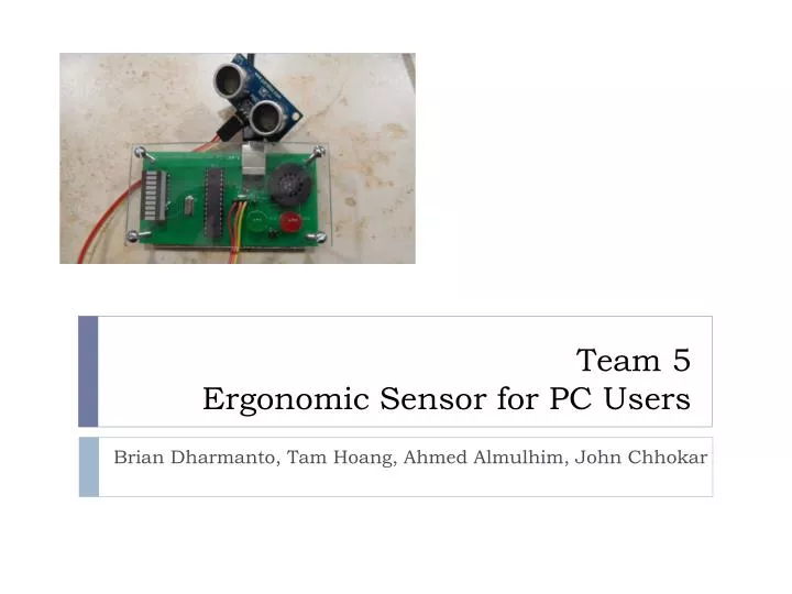
Team 5Ergonomic Sensor for PC Users Brian Dharmanto, Tam Hoang, Ahmed Almulhim, John Chhokar
Agenda • Problem Definition • The Design • Implementation • IP and Prior Work • Testing and Results • Contributions • Lessons Learned
Problem Definition • Number one injury in the office is caused from bad ergonomics. • Companies have started to express a lot of interest in ergonomics as employee lost day cases as increased. • Ergonomics in the workplace focuses on the health and well being of the employees. • Occupational Safety and Health Administration (OSHA) reports that improper viewing distances to the PC can cause eye strain that lead to headaches.
Problem Definition • American Optometric Association (AOA) state that 50-90% of PC users experience Computer Vision Syndrome (CVS). • CVS is defined as a temporary condition resulting from focusing the eyes on a computer screen for uninterrupted periods of time.
Motivation • There is no device on the market that keeps the PC user accountable for operating the PC at a proper viewing distance • The objective is to create such a device that keeps the PC user at a good distance and as a result reduce CVS. • We will focus only on distances which are too close. • Companies are looking at software to improve ergonomics but have yet to come up with a hardware solution
Objective • Goal of the project is to design a working prototype • Secondly the design should be stable such that the user is aware of a bad viewing distance as soon as they approach dangerous viewing distances. • Lastly, the prototype should be at least as small a standard wireless USB mouse.
Alternative • Software: • Flux : Change the color of screen • Eye Defender: Remind user to take a rest after a given time • Screen Protector: Prevent direct expose to UV light
Requirement • Place the ultrasonic on the top of the screen, the sensor must look directly to face of user unless the device will send the incorrect warning.
Approach • 6 steps : • Research • Sensor • Microcontroller code • Prototype • Schematic & Layout • Test
Agenda • Problem Definition • The Design • Implementation • IP and Prior Work • Testing and Results • Contributions • Lessons Learned
Zone Definitions • Green Zone (Safe) : ~ > 18 inches • Red Zone (Danger): ~ < 18 inches • Green Zone Upper Bound: ~ 55 inches
Hardware Type: Microcontroller Atmega 328p 5 volt operating voltage 14 digital I/O pins Programming Language similar to C Cheap No debugging in code is only disadvantage
Hardware Type: Sensor Input PING Ultrasonic Sensor 5 volt operating voltage Relatively low cost Reliable results 3 pin interface
Hardware Type: Output LEDs 2 diffused 10mm LEDs 1 LED Bar Low current Cheap
Hardware Type: Speaker 8 Ω, .1w power Perfect for PCB Board Compact and Light
Measure the distance • The sensor emit a short 40Khz burst then listen for echo. • This burst travel with velocity = 1130 feet/second, hit the object and bounce back • The sensor provide an output pulse to terminate when the echo is detected. Therefore, the width of this pulse correspond to the distance
Agenda • Problem Definition • The Design • Implementation • IP and Prior Work • Testing and Results • Contributions • Lessons Learned
Dimensions • Board: 3.8inch x 2inch • Allowed: 4inch x 3.2inch • Altoids can: 3.5inch x 2.25inch
Agenda • Problem Definition • The Design • Implementation • IP and Prior Work • Testing and Results • Contributions • Lessons Learned
IP • Arduino Development Board http://www.arduino.cc/ • - Used to upload software and debug • Ping Sensor http://www.parallax.com/tabid/768/ProductID/92/Default.aspx • - Datasheet discusses formulas to calculate distances
Agenda • Problem Definition • The Design • Implementation • IP and Prior Work • Testing and Results • Contributions • Lessons Learned
Agenda • Problem Definition • The Design • Implementation • IP and Prior Work • Testing and Results • Contributions • Lessons Learned
Individual Contributors (Ics) Brian Dharmanto • Schematic • Board • Component Solder Ahmed Almulhim • Component Solder • Design of board case • Prototype Tam Hoang • Software • Hardware • Design of sensor case John Chhokar • Software • Prototype • Wiki Admin
Agenda • Problem Definition • The Design • Implementation • IP and Prior Work • Testing and Results • Contributions • Lessons Learned
Lessons Learned • Ahmed Tam • - Software - Sensor Coding • - Solder - Software • - Case Design • John Brian • - SVN - PC BOARD Layout • - WIKI - EAGLE • - Case Design - SMT Solder