Download
1 / 36
360 likes | 485 Views
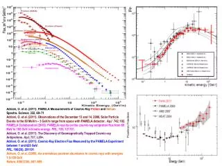
Overview of AMS-02 Changes due the addition of the Permanent Magnet 05/04/2010 Joseph Kastelic / ESCG. AMS-02 Payload Design Changes due to the addition of the Permanent Magnet. Major Cryogenic Hardware Removed from the AMS-02 Payload Superconducting Cryomagnet

E N D
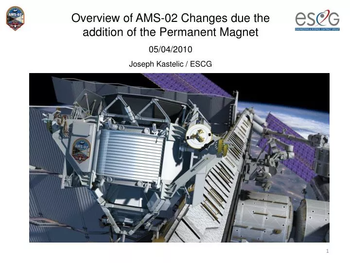
Overview of AMS-02 Changes due the addition of the Permanent Magnet 05/04/2010 Joseph Kastelic / ESCG
AMS-02 Payload Design Changes due to the addition of the Permanent Magnet. • Major Cryogenic Hardware Removed from the AMS-02 Payload • Superconducting Cryomagnet • Superfluid Helium Tank (SFHe) • Cryogenic Support Hardware Removed from AMS-02 Payload • Onboard Vacuum Pump • Cryomagnet Support Straps (suspension system) • Flight Vacuum case • Cryocooler Loop Heat Pipe (LHP) • SFHe Tank Burst Disk • Vacuum Case Burst Disk • CAB Loop Heat Pipe, accumulators, evaporators • Warm Helium Tank and WHT MMOD. • 2500 liters of Liquid/Gas Helium
Major Electrical Hardware removed from AMS-02 Payload • CAB (Cryomagnet Avionics Box) • Cryomagnet Dump Diodes (CDD) • Uninterruptible Power Supply (UPS) • Electrical Support Hardware removed from AMS-02 Payload • Baroswitch Electronics (BSE) • RTD Cabling • Charge/Discharge Cabling • Cryomagnet Pilot Valve Switch (CPVS)(Magic Box) • OBP (Onboard Pump) Cabling from IPA • CCEB electronics (Leave Box On) • Components of the Tracker Alignment System • Major Thermal Hardware Removed from the AMS-02 Payload • Zenith radiator • MLI (Reconfigured for new thermal requirements)
Major Hardware Added to Payload • STA Vacuum Case • Permanent Magnet (Inside the STA Vacuum Case) • Permanent Magnet Support Structure (Inside the STA Vacuum Case) • Tracker Plane 1N (above TRD) • Tracker Plane 6 added between RICH and ECAL • New TTCS loop for Plane 6 • Major Hardware Unaffected by the Change • USS-02 • PAS assembly (except envelope) • Grapple fixtures • Debris Shields • ROEU • EVA Connector Panel • Umbilical Mechanism Assembly • Hardware Reconfigured • Electronic Calorimeter (ECAL) moved 35mm • Tracker Plane 1N relocated above TRD.
External Parts to be Removed From Payload Debris Shield, ROEU, and Interface Panel A removed for clarity Zenith Radiator (Cryomagnet cooling) Cryomagnet Pilot Valve Switch Box (CPVS) BSE (Baroswitch) Cryomagnet Dump Diode (CDD) Cryomagnet Avionics Box (CAB) and CAB Loop Heat Pipe Vent Pump Uninterruptable Power Supply (UPS) Cryocooler
External Parts to be Removed From Payload Cryocooler Vacuum Case Burst Disk SFHe Tank Burst Disks Warm Helium Tank and MMOD Shield Cryocooler
Superconducting Cryomagnet and external Cryogenic Hardware. Most will be removed from the AMS-02 Payload Various Tubes. Fittings, Valves, etc. to be removed. Burst Disk Warm Helium Tank and MMOD Shielding 4 Cryocooler
Cryomagnet Vacuum Case Internal Hardware that will be removed Cryomagnet Helium tank Sixteen Support straps (magnet suspension system)
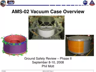
STA Vacuum Case to be Configured for Fight with permanent Magnet
Permanent Magnet originally flow on STS-91 June1998 Mounts to structure with bolts and shear pins in 8 locations on the cylinder and 4 places on each flange Top flange (structural) Bottom Flange (structural) Magnet material core (non-structural)
STA Vacuum Case with Permanent Magnet Support Struts (16) (Titanium Alloy) Permanent Magnet VC Upper and Lower Support rings Aluminum X Structure 7075-T7351 Top View :Struts (exactly along Original Action Line) Conical flanges and Outer Cylinder not shown
STA Vacuum Case with Permanent Magnet Outer Support Structure with 4 Identical Structures VC attachment Fitting Titanium Strut Clevis and Spherical Bearing Joint All Joints: Bolted and Shear Pin AMS02 Permanent Magnet
Vacuum Case with PM Cross Section Upper Conical Flange Upper Support Ring Outer Cylinder Lower Support Ring Permanent Magnet Lower Conical Flange Permanent Magnet X-Structure
Vacuum Case with PM Installed in the AMS-02 Unique Support Structure STA Shown Installed in Pre-Integration Activities
AMS-02 Tracker Assembly (Reconfigured) Tracker Design Prior to PM Tracker Assembly Tracker was Contained within the inner bore of the Vacuum Case
Tracker Consist of 5 Planes of Carbon Fiber and 8 layers of Silicone Relocated Plane 5 or Plane 1N Original Configuration Plane 5 will be moved to the top of the TRD Plane 1: Layer 1 Plane 2: Layer 2 and 3 Plane 3: Layer 4 and 5 Plane 4: Layer 6 and 7 Plane 5: Layer 8 Tracker Plane P9 will be made from parts taken from layer 8, layer 1, and spares. New Tracker Plane 6 Layer 9
AMS-02 Experiment Core and Tracker Assembly Reconfigured Transition Radiation Detector (TRD) Silicone Tracker Ring Image Cherenkov Counter (RICH) Electronic Calorimeter (ECAL)
Plane 1N Configuration Honeycomb Support Structure with CF face sheets Carbon Fiber Plane 1N Silicone layer TRD Plane 1N TRD Plane 1N will include MLI and debris containment.
AMS-02: Upper TRD Cover with Plane1N Support Plane1N Support Structure Unique Support Structure (USS) TRD Permanent Magnet Assembly
AMS-02: Upper TRD Cover with Plane1N Support Plane 1N Plane1N Support Structure shown translucent
AMS-02: Upper TRD Cover with Plane1N Support Honeycomb Support Structure with CF face sheets Silicon Layer Plane1N Plane1N Support
AMS-02: Upper TRD Cover with Plane1N Support Silicon Layer PlatenN Plane1N Support
New Tracker Plane 6 Layer 9 Tracker Lower Time of Flight The empty space from Plane 5 will be replaced with a dummy plane New Tracker Plane will be located between the ECAL and the RICH Assembly The ECAL will be lowered by 35mm giving room for the new plane Plane 6 will include MLI and debris containment.
New Tracker Plane 6 Layer 9 Carbon Fiber Plane Silicone Layer Tracker Plane Mounting Hardware. Interfaces Existing ECAL Mounting Locations ECAL Silicone Layer
New Tracker Plane 6 Integrated New Cooling Loop
New Tracker Plane Cooling Loop Tracker Plane Cooling Loop (TTCS) Loop for Plane 6 (Evaporator)
Capture Bar Clearance issue due to the lowering of the ECAL Capture Claw Clearance Envelope ISS Keep out zone AMS-02 Capture Claw Passive PAS Active Common Attach System (CAS) The Configuration prior to lowering the ECAL
Lowering The ECAL 35mm produces a violation of the Capture Claw Envelope of 19mm There is no known impact of the envelope violation that concerns AMS-02 Nominal Clearance to Claw 24mm
MLI Considerable MLI changes are anticipated. Some will be eliminated and others will be added. Ram Wake Starboard Side of Payload
MLI Considerable MLI changes are anticipated. Some will be eliminated and others will be added. Ram Wake Port Side of Payload
AMS-02 Hardware that will not be changed Power and Video Grapple Fixture (PVGF) Port Debris Shield EVA Handrails USS-02 Assembly (Primary Structure) Umbilical Mechanism Assembly (UMA) Payload Attach System (PAS)
AMS-02 Hardware that will not be changed Remotely Operated Electrical Umbilical (ROEU/PDA) Starboard Debris Shield Flight Releasable Grapple Fixture (FRGF) Interface Panel A USS Handrails Keel Assembly EVA Connector Panel Keel Handrails