Download

1 / 59
610 likes | 799 Views
Pumping Plants. Types of Pumps. Positive displacement pumps Rotary (gear, screw, etc.) Reciprocating (piston, diaphragm, etc.) Used as injection and sprayer pumps, but not for irrigation water Centrifugal pumps

E N D
Types of Pumps • Positive displacement pumps • Rotary (gear, screw, etc.) • Reciprocating (piston, diaphragm, etc.) • Used as injection and sprayer pumps, but not for irrigation water • Centrifugal pumps • Rotating impeller converts mechanical energy into hydraulic energy (show examples and transparency)
Rotating Impeller Converts Mechanical Energy to Hydraulic Energy
Centrifugal Pump Impellers Enclosed Impeller Semi-Open Impeller
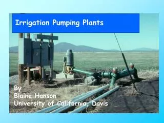
Centrifugal Pumps • Horizontal • Drive shaft is horizontal • Often used when pumping from a surface source (pond, lake, stream, etc.), Or for boosting the pressure in an irrigation pipeline (booster pump) • Usually sold as completely assembled units
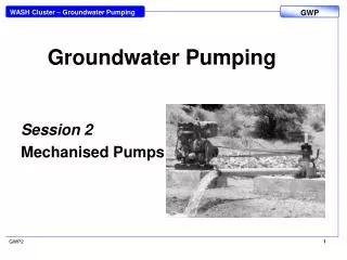
Centrifugal Pumps, Contd... • Vertical Turbine • drive shaft is vertical • used when pumping from a well • normally custom built from components (with multiple stages) • submersible: electric motor below the lowest stage
Single-Stage Vertical Turbine Pump Water Flow Path Through a One-Stage Vertical Turbine Pump
Two-Stage Vertical Turbine Pump Water Flow Path Through a Two-Stage Vertical Turbine Pump
(Discharge Heads) Gearhead for engine drive Holloshaft electric motor
Submersible Water Pumps • Same as vertical turbine pump design • Driven from below by electric motor • Good for deep wells • High efficiency • Wells as small as 4” diameter
Pump Characteristics • Head vs. discharge • discharge (or capacity): volume of water pumped per unit of time (gpm) • head (or total head or total dynamic head): • energy added to the water by the pump • units of feet (energy per unit weight of water
Pump Characteristics Cont’d… • Pump Efficiency vs. Discharge Power = energy/time; 1 HP = 33,000 ft-lb/min • Q in gpm; TDH in ft, whp in horsepower - whp = power added to the water by the pump
Pump Characteristics Contd… • Brake horsepower vs. Discharge where: Q, (gpm); TDH, (ft); bhp & whp, (HP) • Combined characteristic curves • Horizontal centrifugal pump • Vertical turbine pump
Affinity Laws • Speed • Law applies to virtually all irrigation pumps • Ep may be affected a little, but not as predictable • Ways of changing speeds: pulleys, gear ratios, throttle, change motor
Affinity Law Example A pump operating at 1800 RPM delivers 200 gpm at a TDH of 150 feet and requires 10 HP to operate. What will be its Q, TDH and BHP conditions if it is sped up to 2000 RPM? RPM1=1800 RPM2= 2000 RPM2/RPM1=1.11 Q2/Q1= RPM2/RPM1 Q2= Q1 x RPM2/RPM1 = 200 x 1.11= 222 gpm TDH2/TDH1=[RPM2/RPM1]2 TDH2= TDH1 x [RPM2/RPM1]2 TDH2 = 150 x [1.11]2 = 185 feet BHP2/BHP1 = =[RPM2/RPM1]3 BHP2= BHP1 x [RPM2/RPM1]3 BHP2= 10x [1.11]3 = 13.7 HP
Affinity Laws Contd… • Impeller diameter • Law strictly applies only to horizontal centrifugal pumps, but good approximation for vertical turbine pumps • Ep may change a little • Diameter is changed by trimming the impeller (law holds up to about 10-20% trim)
Pumps in Series • Booster pump • Multi-stage turbine pump • Q1 = Q2 • TDHtot = TDH1 + TDH2 (add heads at the same discharge) • bhptot = bhp1 + bhp2
Pumps in Parallel Contd… • Qtot = Q1 + Q2 (add discharges at the same head) • bhptot = bhp1 + bhp2
Pump Selection • System Head • Definition: • Total head imposed on a pump by the irrigation system also called TDH (Total Dynamic Head), total pumping head, etc. • Components • Static Head (Elevation Head): elevation difference between water level on the inlet side and the water delivery point
Components Cont’d… • Pressure Head: difference in water pressures between the source and the delivery point • Friction Head: total friction loss between the source and the delivery point • Velocity Head: V2/(2g) (usually considered negligible) • System Head = Static + Pressure + Friction (units of feet)
Components of Total System Head (or Total Dynamic Head, Total Pumping Head)
System Head Curve • H increases with increasing Q because of: • drawdown (wells) • friction • pressure at nozzles • System head can also vary with time: • water table fluctuations • changes in the irrigation system • pipe aging
Pump Operating Point • As indicated by its TDH-Q curve, a pump can operate at many possible points • A pump will operate at a Q and TDH determined by the point where the pump curve and the system head curve cross • The same pump is likely to operate at two different TDH-Q combinations when placed in two different irrigation systems
Matching a Pump to the System • General • buyer specifies desired Q and TDH (usually not the entire system head curve) • supplier specifies operating characteristics (including pump curves) • obviously want a high Ep • can fine tune a match by adjusting speed and/or trimming the impeller
Matching a Pump to the System Contd… • Horizontal Centrifugal Pumps • provide correct Q and TDH at a high Ep • usually buy off-the-shelf unit • Vertical Turbine Pumps • choose a bowl and impeller to provide the desired Q at a high Ep • determine the number of bowls required to provide the desired TDH (pumps in series)
A vertical turbine pump is needed to deliver 400 gpm from a well that will have a static pumping lift of 237 feet, plus an operating pressure of 55 psi at the pump head. Is the WLR 10JKH pump below a good choice? If so, how many stages are required? TDH= 237+(55psi*2.31 ft/psi)=364 ft @ Q=400 gpm: TDH=52 ft/stage for 7.7” & Ep=79.5% TDH=41 ft/stage for 7.13” & Ep=77.5% TDH=30 ft/stage for 6.56” & Ep=72% 364 ft/52 ft/stage=7 stages The best choice is the 7.7” diameter impeller at 52 ft/stage, because it not only requires the fewest stages (low initial cost), but has the best efficiency (low operating cost) near 80%.
A vertical turbine pump is needed to deliver 400 gpm from a well that will have a static pumping lift of 237 feet, plus an operating pressure of 60 psi at the pump head. Is the WLR 10JKH pump below a good choice? If so, how many stages are required? TDH= 237+(55psi*2.31 ft/psi)=364 ft @ Q=400 gpm: TDH=52 ft/stage for 7.7” & Ep=79.5% TDH=41 ft/stage for 7.13” & Ep=77.5% TDH=30 ft/stage for 6.56” & Ep=72% 364 ft/52 ft/stage=7 stages The best choice is the 7.7” diameter impeller at 52 ft/stage, because it not only requires the fewest stages (low initial cost), but has the best efficiency (low operating cost) near 80%.
Net Positive Suction Head • Suction lift and cavitation • Handout • Pump does not "suck" or "pull" water • Impeller causes partial vacuum • Atmospheric pressure forces water up to the impeller • Theoretical vs. practical lift • Describe cavitation
NPSHa • NPSHa = AP - SL - FL - VP • AP = atmospheric pressure • SL = suction lift (vertical distance) • FL = friction loss on suction side • VP = vapor pressure • all have units of feet
NPSHr • NPSHr is a pump characteristic (increases as Q increases) • If NPSHa > NPSHr: Design is OK • If NPSHa < NPSHr: Cavitation will be a problem (good idea to have a factor of safety)
Power Units • Electric motors • direct coupled • High Efficiency drive (Edrive=100%), but Fixed Speed • belt drive • Variable Speed, but Lower Efficiency drive (Edrive= 90%) • rated by output HP • Em's 90% are common • Em doesn't vary much with load (unless it's significantly under-loaded)
Internal Combustion Engines • Fuels • Natural gas • Diesel fuel • Propane • Gasoline • Right-angle Gear Drives • Convert power in horizontal engine shaft to power in vertical pump line shaft • Edrive 95% (5% loss through the gear drive)
Internal Combustion Engines Contd… • Ee varies with engine speed and with the load on the engine • Ee's rarely exceed 30%
Pumping Costs Fixed Costs vs. Operating Costs • Fixed: pump, motor/engine, well, other equipment (total cost is the same regardless of use) • Operating: energy, maintenance, repairs, labor (total cost increases with increasing use)
Overall Pumping Plant Performance Overall pumping plant efficiency, (Eo): Electric Motor Driven • Eo = Ep x Em x Edrive Internal Combustion Engine Driven • Eo = Ep x Ee x Edrive Efficiencies are expressed in decimal for this calculation, (%/100)