Download
1 / 34
340 likes | 457 Views
EURATOM Association. LT WS (W56) on Physics of Current Holes, Mito, Japan, 3-4 Feb 2004. Current holes at ASDEX Upgrade. Presented by O. Gruber for D. Merkl, J. Hobirk, P.J. McCarthy, E. Strumberger, ASDEX Upgrade Team. - hardware upgrades for improved control - integrated advanced scenarios

E N D
EURATOM Association LT WS (W56) on Physics of Current Holes, Mito, Japan, 3-4 Feb 2004 Current holes at ASDEX Upgrade Presented by O. Gruber for D. Merkl, J. Hobirk, P.J. McCarthy, E. Strumberger,ASDEX Upgrade Team - hardware upgrades for improved control - integrated advanced scenarios - ion ITB with current hole: equilibrium, current diffusion - electron ITB with current hole - summary
Electron Cyclotron Resonance Heating: 2 MW / 140 GHz / 2 s 4 MW / 105 -140 GHz / 10 s - on-line steerable mirrors ASDEX Upgrade R= 1.65 m a = 0.5 m Ip 1.4 MA Bt 3 T PNI 20 MW PICRH 8 MW PECRH 2 MW ASDEX Upgrade: flexible heating and fuelling systems Pellet Centrifuge: 240 - 1000 m/s repetition rate 80 Hz Neutral Beam Injection: - perp. heating 15 MW / 70-100 keV - tang. off-axis beams 5 MW/ 100 keV • Ion Cyclotron • Resonance Heating: • 8 MW / 30-60 MHz • - variable deposition
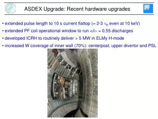
recent hardware upgrades improved control - extended pulse length to 10 s flattop (= 2-3tR even at Te(0) =10 keV) - extended PF coil operational window to run <d> = 0.55 discharges - developed ICRH to routinely deliver > 5 MW in ELMy H-mode - increasing W coverage of inner wall First wall materials need minimum erosion & low Tritium retention ●stepwise towards C-free interior - in 2004 campaign70% of first wall covered - W-divertor in upper SN C-divertor in lower SN ●Up to now: - all plasma scenarii still accessible usually W concentration below 10-5 - machine has been more ‚delicate‘ to run central RF heating & ELM control by pellets suppresses impurity accumulation at improved core confinement W W W W W
Next hardware extensions • Towards a C-free first wall: • - W coating of LFS poloidal limiters (actively cooled) 2004 • - W coated bottom divertor 2005 • Off-axis CD • - upgrading of ECRH started • (4 MW / 10 s / steerable mirrors / 105–140 GHz ) • - LHR system (3.7 GHz) in discussion
Next hardware extensions MSE,... NI I YAG ECRH CX/ LHR passive shell DCN TNBI A9 current feeders ? • Stabilizing shell for external kinks & active RWM control shell time constant for n = 1 above 30 – 40 ms (d=3 cm, steel) 2 sets of 8 active toroidal coils (n = 1, 2)
Next hardware extensions ECRH MSE,... YAG TNBI A9 passive shell CX/ LHR A9 DCN ECRH NI I current feeders ? • Stabilizing shell for external kinks & active RWM control CAS-3D (P. Merkel): - shell currents for n=1 kink - extension to resistive wall - benchmarking with resistive 2d-wall code
Performance beyond H-mode: integrated "advanced" scenarios More compact pulsed reactor / steady-state operation H89-P N / q95> 0.8 Aim to achieve these conditions in steady state: - energy and particle exhaust need nenGW - tolerable ELMs bootstrap current fraction > 50%in stationaryadvanced H-mode: prime candidate for ´hybrid´ ITER scenario BS fraction > 80% for continuous reactor operation: strong ITBs with reversed shear needed 2 H89-P ITER bN
ITBs produced in the current ramp-up with strong reversed shear • at JET (using LHCD) and JT-60U (using NBI) showed the existence • of an extended core region with zero toroidal current: current holes • open questions: equilibrium, stability, transport, sustainment • influence of size: duration limited by skin effect ? • ITB driven bootstrap current sufficient? • full non-inductive current drive needed for sustainmen t? (0.8 MA, 2.7 T) Motivation for current hole investigations
Ion ITB discharge with current hole barrier extends over the qmin region ITB driven bootstrap current and shear profile can be aligned
Ion ITB discharge with current hole: MSE results current hole lost when third source switched off (ITB lasts longer) DTM magnetic axis geometry formula of MSE at ASDEX Upgrade
current hole: equilibrium reconstruction • Cliste: • solves Grad-Shafranov equation using external magnetics and MSE data • cubic spines for basic functions prevents sharp „current hole“ edge • uses poloidal flux y as main coordinate • for very low central current densities, rpol = y as a function of • spacial coordinates is poorly defined convergence problems • new version: rmid rtor • weighted sum of previous solutions for y(R,z) and j(R,z) • during iteration to improve convergence • (successive ´over-relaxation´) • NEMEC: • modified 3-d stellerator equilibrium code (S.P. Hirshman) • energy minimizing fixed / free boundary code assuming nested flux surfaces • uses toroidal flux as main coordinate
current hole: equilibrium reconstruction • good agreement of the q-profiles except of the current hole edge • measured position of the (2,1) DTM from SXR & ECE
current hole: equilibrium reconstruction - colored points are the MSE observation points - shaded area labels the current hole Comparison of equilibrium reconstruction with MSE measurements
current hole: current diffusion • ITB driven off-axis bootstrap current not sufficient to maintain current hole • initial current hole taken from CLISTE at 0.3 s vanishes within 100 ms • fast diffusion of beam current density ? • high fast particle content may contribute to BS current
current hole: confinement - reversed magnetic and velocity shear improve heat insulation in core T driven transport suppressed internal transport barriers (ITBs) - stored energy of ion ITBs increases linearly with heating power
Electron and ion ITB Ctr-ECCD • no MSE available • sawtooth-like crasches in Te due to collapsing electron ITBs during ctr-ECCD: • indicates strong reversed shear (previous AUG results) or current hole (JET)
Combined electron and ion ITB • early ctr-ECCD produces electron ITB • at delayed NBI onset, ion ITB develops • combination of electron and ion ITB • foot of electron ITB sits at smaller radius
Small current hole during on-axis ctr-ECCD (ASTRA) TORBEAM: IECCD=70 KA
Summary • extended control tools for all scenarii: - operation at high shaping • -variable schemes for profile control (pressure, momentum, density, j, impurities) • - variety of methods for NTM suppression • - ELM control via shaping (type II ELMs), QH-mode and pellet pacemaking • - kink and RWM control envisaged • current holes in ion ITB discarges (early NI heating) observed: - current hole diameter up to 25% of minor radius - equilibrium reconstruction with CLISTE (convergence up to q0 40) and NEMEC (q0 > 1000) possible • -ASTRA current diffusion simulations show no sustainment by off-axis BS current • - anormal beam driven current diffusion & fast particle BS needed: • - off-axis co-CD supports: • current hole lost with switch-off of tangential off-axis beam • current holes with on-axis ctr-ECCD: • - electron ITBs • - combined electron and ion ITBs with both ECCD and NBI (Ti Te 8 - 10 keV) • - ASTRA simulations indicate small current hole during central ctr-ECCD
Advanced H-modes: performance Improved H-mode High bN Improved H-mode High bN q95 = 3.3 - 4.3 q95 = 3.3 - 4.3 1.5 4 H98(y,2) bN 3 1.0 2 bN = 1.8 1 0.5 0 0.2 0.4 0.6 0.8 1.0 1.2 0.2 0.4 0.6 0.8 1.0 1.2 ne/nGW ne/nGW n* reactor relevant at medium densities :H89-P= 2.8, bN= 3.2 (IAEA1998) optimum exhaust close to Greenwald : H89-P= 2.4, bN = 3.5(H-mode WS 2001) (at q95= 3.5) - continuous transition
Advanced H-modes: progress towards steady state & adv. performance advanced advanced best combination of confinement, stability and density at high d > 0.4 and q95 3.5 higher q95 over-compensated by enhanced performance ITER ITER 2 N H98-P / q95 = 0.35 (0.2 in conv. ITER) Steady conditions for many current redistribution times: low n* - tripple product 1020 m-3keV s-1 - QDT(equivalent) 0.2 high Greenwald fraction
ITBs: missing stationarity due to MHD events Decisive influence of scenario: H89-P • ITBs with early heating and RS - limited by coupling of infernal (at qmin 2) and extrnal kinks to bN< 2 • ITBs with delayed heating - highest performance achievable - high performance terminated by ELMs • Combined electron and ion ITBs - high performance terminated by central 2/1 MHD ITER bN • sustained only with L-mode edge or poor H-mode edge • at better performance discharges short compared with current diffusion time • high control efforts required: p, j, MHD modes • a self-consistent scenario with reduced control requirements exists
Can tokamaks be optimised towards continuous reactor? • high pressure gradient needed to get 80% bootstrap current fraction(Q >30) • reversed magnetic and velocity shear improve heat insulation in core • T driven transport suppressed internal transport barriers(ITBs) • ITB driven bootstrap current and reversed shear profile can be aligned • optimise MHD stability – high p-gradient at q(min) leads to global MHD modes • combination of electron and ion ITB scenarii needed - foot of ITB at r = 0.6
Can tokamaks be optimised towards continuous reactor? • reversed magnetic and velocity shear improve heat insulation in core • T driven transport suppressed internal transport barriers (ITBs) • high pressure gradient needed to get 80% bootstrap current fraction (Q > 30) • ITB driven bootstrap current and reversed shear profile can be aligned • optimise MHD stability: high p-gradient at q(min) leads to global MHD modes • combination of electron and ion ITB scenarii needed • early ctr-ECCD produces electron ITB • at delayed NBI onset, ion ITB develops • foot of electron ITB sits at smaller radius
Ion ITBs:barrier position and q profile aligned r(qmin) rpol - MHD modes trigger ITBs relation with rational q values - strong barriers only in connection with reversed magnetic shear • barrier extends over the qmin region ITB driven bootstrap current and shear profile can be aligned
Ion ITBs: route to very high bootstrap fractions • ITB scenario with delayed heating: • - heating of 15 MW late in the current ramp • lower SN with high triangularity • transition to H-mode 0 1 t(s)
Ion ITBs: route to very high bootstrap fractions • first large ELM destroys ITB ! • ITB scenario with delayed heating: • - heating of 15 MW late in the current ramp • lower SN with high triangularity • transition to H-mode 800 kA: ne/nGW=0.45 No-wall limit reached !?bN = 4.0 H89-P = 3.2 Tio = 14 keV 1 MA: Tio > 20 keV 1.5.1020 m-3keV s-1 ≥ 60 % BS current
Can tokamaks be optimised towards continuous reactor? • early ctr-ECCD produces electron ITB • at delayed NBI onset, ion ITB develops • foot of electron ITB sits at smaller radius
Summary (1) • Extended control tools for all scenarii: - 10 s flat-top pulses allow current profile relaxation - operation at high triangularities close to DN (d = 0.55 achieved) • -variable heating / CD schemes for profile control • (p, momentum, density, j, impurities) • Active MHD control: • - variety of methods for NTM suppression • - ELM control via shaping (type II ELMs), QH-mode and pellet pacemaking • reduced target loads, impurity control • - kink and RWM control envisaged • - disruption mitigation (not covered) Highest performance achieved in Ion ITBs with reversed shear - scenario extended to high confinement H89-P= 3.4 and high beta bN= 4 - Ti Te 8 - 10 keVwith ctr-ECCD and NI - duration limited by strong ELMs, core and edge MHD modes - up to now transient max performance not sustainable - benchmark is advanced H-mode scenario
Summary (2) • Advanced H-mode scenario: a basis for ITER hybrid operation (even steady-state or ignition possible) • - relaxed low shear q-profile (long sustainment compared to res. diffusion) • - control of density peaking & impurity accumulation with tailored heat dep. • - enhanced confinement H98-P= 1.1 - 1.5 and beta bN> 3 (up to no-wall limit) • over substantial operational range of q95 , d and density • - integration of type II ELMs close to Greenwald density and double null • - despite high densities, > 60% non-inductive current drive achieved • stepwise towards C-free interior (reduced erosion, T retention) • - all advanced plasma scenarii accessible with W concentration below 10-5 • - impurity accumulation at improved core confinement suppressed • with central RF heating & ELM control by pellets