Download
1 / 20
200 likes | 278 Views
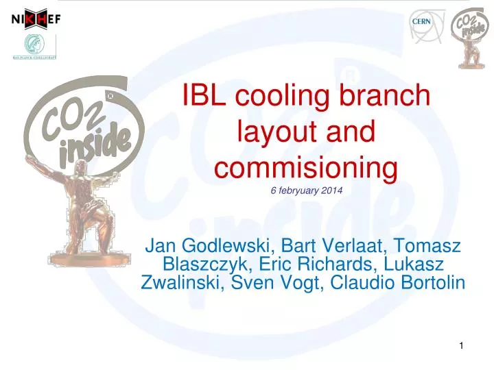
IBL cooling branch layout and commisioning 6 febryuary 2014. Jan Godlewski, Bart Verlaat, Tomasz Blaszczyk , Eric Richards, Lukasz Zwalinski , Sven Vogt , Claudio Bortolin. Detector boundary. LAR Cryo area. Junction box @ Muon Sector 5 (Accessible). Transfer tubes (~92m).

E N D
IBL cooling branch layout and commisioning6febryuary2014 Jan Godlewski, Bart Verlaat, TomaszBlaszczyk, Eric Richards, LukaszZwalinski, Sven Vogt, ClaudioBortolin
Detector boundary LAR Cryo area Junction box @ Muon Sector 5 (Accessible) Transfer tubes (~92m) CO2: 10x1mm inside 21.3x2.11mm outside BD016 PT116 / PT316 TT116 / TT316 ⅜” HX036 Dummy load (testing only) ¾”x5/16” MV036 MV018 MV017 ½” EH117 TT117 TS117 BD036 PT136 / PT336 TT136 / TT336 FL018 FL017 36 26 34 30 30 28 26 20 22 28 24 32 32 16 06 08 04 BD020 PT120 / PT320 TT120 / TT320 ¼” AV017 ⅜” MV035 ½” TTz36 (DCS) TTz20 (DCS) ⅜” Manifold box (S5) HX012 DN40 vacuum Vacuum system (LAR Cryo area) EH122 TS122 DN40 USX-15 DCS: TTa24 - TTn24 MVa24 - MVn24 D012 USA-15 Tile calorie meter LAR calorie meter Tracking detectors DCS: TTa28 – TTn28 DCS: TTa30 – TTn30 14 IBL staves (a-g),(7 flow pairs) (7x A-›C flow / 7x C-›A flow) Dry volume A200 A100 B400 B300 C042 BV,28-01-2014
Seen from C-side C to A C to A Flow orientation A to C A to C C to A A to C
Flex line A1…A7 Seen from A-side 7 6 5 4 3 2 1 Splitter box Tube color Splitter box color 3 Stave 2 Stave 1 6 14 12 11 Designed by Lapp and lpnhe
Flex line C1…C7 Seen from c-side 1 2 3 4 5 6 7 Splitter box Splitter box color Tube color 3 Stave 2 Stave 1 6 14 Designed by Lapp and lpnhe 12 11
Flex line arrangement in manifold Manifold seen from C-side In= vapor in from stave Out=Liquid out to stave A1, 12 in, 13 out A2, 14 in, 1 out A3, 2 in, 3 out A4, 4 in, 5 out A5, 6 in, 7 out A6, 8 in, 9 out A7, 10 in, 11 out C1, 13 in, 12 out C2, 1 in, 14 out C3, 3 in, 2 out C4, 5 in, 4 out C5, 7 in 6 out C6, 9 in, 8 out C7, 11 in, 10 out To A-side To C-side
Flex line commissioning • Connection sequence: • Route lines • Connect rotatable connector to manifold box (both vacuum and CO2) • Leave IBL lines disconnected from detector but in vicinity. • Test vacuum system with lines attached. • Pressure test flex lines • Connect CO2 from junction box • Perform flow tests with warm CO2 (~15’C) using inter connects • Empty lines and connect to IBL • Fill with CO2 and ready for IBL cooling test
Vacuum transfer line(From S5 to IDEP) We have to grasp the bundle from under-neath the muons and bend it in place Ca. 11m long Super insulation 7x 4mmOD / 3mmID outlet tube 50mm PVC tube mock-up 7x 1.6mmOD / 1.0mmID concentric inlet tube 7x 16mmOD vacuum hose
IDEP Side A A Mock-up tubes, may not be covered with cables or so. IDEP cover fit check B B A
IDEP Side C B Mock-up tubes, may not be covered with cables or so. A B IDEP cover fit check A
Sector 5 area (Junction box andmanifold) Manifold box To cooling plant in USA Junction box The junction box contains a dummy heater for commissioning and has valves to close off the IBL. Also accessible filters are present. Flex lines to IBL Tomasz Blaszczyk
Manifold box How to connect and disconnect a cooling line
flexline IBL side Manifold box side 11meter Sven Vogt