Download
1 / 36
430 likes | 715 Views
Downhole Pressure Monitors. Halliburton Pressure Transmission Systems (PTS) have been in use at SYU since 1984 (Hondo) & 1993 (Harmony & Heritage) Have installed over 60 downhole pressure gauges

E N D
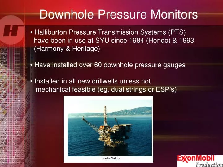
Downhole Pressure Monitors • Halliburton Pressure Transmission Systems (PTS) have been in use at SYU since 1984 (Hondo) & 1993 (Harmony & Heritage) • Have installed over 60 downhole pressure gauges • Installed in all new drillwells unless not mechanical feasible (eg. dual strings or ESP’s)
Platform Hondo is located in offshore California in the Santa Barbara Channel. The water depth is between 900' and 1200'. Hondo was discovered in 1968 and the initial production began in 1981 Presently 26 active wellbores. 14 Wells that are on gaslift or 54% of the total active wellbores
Platform Heritage is located in offshore California in the Santa Barbara Channel. The water depth is between 900' and 1200'. Heritage was brought on line in 1993. Presently 39 active wellbores. 28 Wells that are on gaslift or 72% of the total active wellbores.
Background Harmony Platform is located in offshore California in the Santa Barbara Channel. The water depth is between 900' and 1200'. Harmony was brought on line in 1993. Presently 31 active wellbores. 23 Wells that are on gaslift or 74% of the total active wellbores.
Gas Lift Optimization Using Downhole Pressure Monitors • Downhole gauges can measure downhole pressure at depth real time • Can change any condition (eg. Choke position, g/l rate, viscosity reducer) and immediately see effect on downhole pressure • If downhole pressure increases then drawdown has decreased therefore we know fluid rate has decreased • If downhole pressure decreases then drawdown has increased therefore we know fluid rate has increased • Can change g/l rate and viscosity reducer and immediately determine if there is an impact on rate
Example of Gas Lift Optimization at SYU When the gas lift rate was changed from 1.2 to 1.4MCFD. The flowing BHP fell from 895 to 890 psi.
Reservoir Surveillance Using Downhole Pressure Monitors • With downhole gauge can measure shut in downhole pressure by simply shutting in well and measuring fluid level using echometer • Knowing fluid level we can adjust pressure at the gauge to either the perforation depth or datum depth • We can get a shut in pressure whenever the well is shut in with no mechanical risk from using wireline in the hole • These pressures are used to determine if reservoir is being depleted too quickly and we need injection of gas or water
Completion Surveillance Using Downhole Pressure Monitors • With downhole gauge can perform a pressure buildup test everytime the well is shut in • With the data from the pressure buildup test reservoir engineer or service co. can determine the productivity of the well (PI) and well damage (skin) • With this analysis we can determine how effective the completion is and then determine if remedial work is required such as acid stim or scale treatment, etc. • If you have multiple gauges can use to calibrate and validate your wellbore hydraulic model (NODAL)
PTS Pressure Transmission System Technology Review
What is PTS? • An economic alternative method to electronic gauges for the monitor of down hole pressures • Uses a gas filled capillary tube to convey bottom hole pressure to surface monitor • Halliburton has applied this proven technology for 30 nearly years
Pressure Transmission System (PTS) No Electronics No Moving Parts
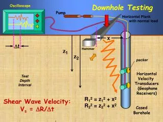
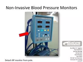
PressureMonitoring Equipment Capillary tubing theory is based on a closed system at the top and an open system on bottom. Such as covering a straw and pushing down into fluid GAS Without a seal at the top, fluid enters to the same height as outer fluid level and no force is exerted at the top Very little fluid enters the straw and a force is exerted at the top of the straw Pack-Off Capillary Tubing Pressure Chamber Chamber Ports Capillary Tubing Theory
PressureMonitoring Equipment GAS Well Bore Gas Pressure Gas is bubbled over and the fluid level inside the system is pushed to the bottom of the chamber After the gas has equalized with the BHP, the injection of gas is stopped + Well BoreFluid Pressure = Compressed Gas Pressure in System to Monitor BHP Capillary Tubing Theory
Gas Movement Inside Chamber When Pressure Increases Fluid Rises In Chamber. Our Goals Is To Not Let Fluid Enter the Capillary Tubing When Pressure Drops To Lowest Point Chamber Is Full Excess Gas Escapes
PressureMonitoring Equipment GAS Gas correction example. Uncorrected BHP 1000 PSI Weight of Gas 20 PSI True BHP 1020 PSI Gas Weightneeds to be corrected for.This calculation uses TVD and Temperature. Capillary Tubing Theory
Gas Correction Factors • Gas weight will change with temperature and pressure • Gas correction uses True Vertical Depth (TVD) of the chamber not the Measured Depth (MD) • Helium is used whenever possible as the system gas • Helium has a liner compressibility with temperature and nitrogen does not. • Nitrogen is approximately 7 times the weight of helium
Gas Correction with and without DTS • With DTS we can use real time temperature changes to correct for the weight of the gas column • If no DTS system is used, we must use an average temperature to correct for the weight of the gas. • The average temperature can be derived from previous surveys or by logging well with a temperature tool. • The corrected pressure can be derived thought post processing of the raw data.
Gas Corrections Example Helium This shows the difference if we corrected the pressure assuming an average temperature of 170 deg F but the actual temperature was 120 deg F TVD 9000 ft
System Accuracy • System accuracy is based on correction of gas weight, transducer accuracy and the fluid level change in the chamber. • Gas weight calculations are as accurate as we are to knowing the average temperature. • Transducer accuracy is based on the type of transducer that is installed. • System resolution .02 to .05 PSI
System Accuracy • Quartz Transducer. • Accuracy of ± 0.015%FS to 0.02%FS • Resolution of 0.01 psi • Drift • At surface temperatures (< 85°C) .001 % FS/yr • 150 to 200 C ,02% FS/yr • Strain Gauge • Accuracy of ± 0.04% FS • Combined Non-linearity, Hysteresis and Repeatability: +0.04 Best Straight Line (BSL) (option A) • Stability: 0.1% F.S./annum
PTS Advantages • No Downhole Electronics • All downhole components are free of electronic parts nothing to get damaged after installation • Suitable for Harsh Environments • Temp > 800F • Corrosives well conditions • Vibration resistant • Check System Integrity From Surface • Transducers and data recording devices can be checked from surface without well intervention • Chamber integrity can be checked without system retrieval • Flexible • System can be installed in many configurations • System can be installed with DTS options
PTS Advantages • Accurate • Quartz/Strain Pressure Gauge • Correction of helium gas column either in real time orpost processing • Rugged • The parts can be installed, removed and reran into same or other wells • Long track record • Easy to Install and Maintain • The system can be installed and maintained by non engineered personnel • Wellhead Penetration Simplicity • Wellhead exits use standard fittings • Most wellhead companies already have designs for control line exits • Wellhead penetration is economic
PTS Advantages • Splices and Connections • Splices are done quick and easy with tube to tube unions • Connections are none electronic and only require ferrule type fittings • Economic Pricing • Systems typically run 50% to 75% of typical EDHG systems
System Maintenance Concerns • Maintenance • What is required • Purging and leak checking • Transducer checks • Frequency of maintenance • Depends on testing we recommend one per Qtr minimum
Downhole Equipment Used at ExxonMobil SYU
SYU Typical Installation Surface Equipment Real Time Pressure Read-out 1/8” Capillary Tube (Pressure) 1/4” Safety Valve Tube 3/8” Chemical Injection Tube Chamber Internal Sensing
Capillary Tubing Extended Chamber DesignInternal Sensing Internal Sensing Ports are on the inside tubing of the chamber
ExxonMobil SYU Project Overview • Starting Dates • Hondo 1984 • Heritage & Harmony 1993 • Installation Types Quantities • PTS Pressure System 60 • Chemical Injection 46 • Subsurface Safety Valves 86 • 1” Diluent Tube 9 • Maximum Installation Depth 19,400 ft • Failures (PTS System) 1