Download
1 / 13
130 likes | 302 Views
Module 3: F28x –Digital I/O. 32-Bit-Digital Signal Controller TMS320F2812. Texas Instruments Incorporated European Customer Training Center University of Applied Sciences Zwickau (FH). GPIO A Direction Control Register (GPADIR). GPIO A Mux Control Register (GPAMUX). GPIO A.

E N D
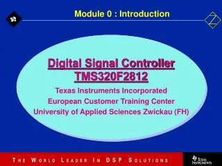
Module 3: F28x –Digital I/O 32-Bit-Digital Signal Controller TMS320F2812 Texas Instruments Incorporated European Customer Training Center University of Applied Sciences Zwickau (FH)
GPIO A Direction Control Register (GPADIR) GPIO A Mux Control Register (GPAMUX) GPIO A GPIO B Direction Control Register (GPBDIR) GPIO B Mux Control Register (GPBMUX) GPIO B GPIO D Direction Control Register (GPDDIR) GPIO D Mux Control Register (GPDMUX) GPIO D Internal Bus GPIO E Direction Control Register (GPEDIR) GPIO E Mux Control Register (GPEMUX) GPIO E GPIO F Direction Control Register (GPFDIR) GPIO F Mux Control Register (GPFMUX) GPIO F GPIO G Direction Control Register (GPGDIR) GPIO G Mux Control Register (GPGMUX) GPIO G GPIO A, B, D, E include Input Qualification feature C28x GPIO Register Structure
GPIO A GPIOA0 / PWM1 GPIOA1 / PWM2 GPIOA2 / PWM3 GPIOA3 / PWM4 GPIOA4 / PWM5 GPIOA5 / PWM6 GPIOA6 / T1PWM_T1CMP GPIOA7 / T2PWM_T2CMP GPIOA8 / CAP1_QEP1 GPIOA9 / CAP2_QEP2 GPIOA10 / CAP3_QEPI1 GPIOA11 / TDIRA GPIOA12 / TCLKINA GPIOA13 / C1TRIP GPIOA14 / C2TRIP GPIOA15 / C3TRIP GPIO B GPIOB0 / PWM7 GPIOB1 / PWM8 GPIOB2 / PWM9 GPIOB3 / PWM10 GPIOB4 / PWM11 GPIOB5 / PWM12 GPIOB6 / T3PWM_T3CMP GPIOB7 / T4PWM_T4CMP GPIOB8 / CAP4_QEP3 GPIOB9 / CAP5_QEP4 GPIOB10 / CAP6_QEPI2 GPIOB11 / TDIRB GPIOB12 / TCLKINB GPIOB13 / C4TRIP GPIOB14 / C5TRIP GPIOB15 / C6TRIP GPIO D GPIOD0 / T1CTRIP_PDPINTA GPIOD1 / T2CTRIP / EVASOC GPIOD5 / T3CTRIP_PDPINTB GPIOD6 / T4CTRIP / EVBSOC GPIO E GPIOE0 / XINT1_XBIO GPIOE1 / XINT2_ADCSOC GPIOE2 / XNMI_XINT13 GPIO F GPIOF0 / SPISIMOA GPIOF1 / SPISOMIA GPIOF2 / SPICLKA GPIOF3 / SPISTEA GPIOF4 / SCITXDA GPIOF5 / SCIRXDA GPIOF6 / CANTXA GPIOF7 / CANRXA GPIOF8 / MCLKXA GPIOF9 / MCLKRA GPIOF10 / MFSXA GPIOF11 / MFSRA GPIOF12 / MDXA GPIOF13 / MDRA GPIOF14 / XF GPIO G GPIOG4 / SCITXDB GPIOG5 / SCIRXDB C28x GPIO Pin Assignment Note: GPIO are pin functions at reset GPIO A, B, D, E include Input Qualification feature
15 - 8 7 - 0 reserved QUALPRD GPxQUAL 00h no qualification (SYNC to SYSCLKOUT) 01h QUALPRD = SYSCLKOUT/2 02h QUALPRD = SYSCLKOUT/4 FFh QUALPRD = SYSCLKOUT/510 . . . . . . . . . C28x GPIO Functional Block Diagram GPxSET GPxCLEAR GPxTOGGLE Primary Peripheral Function GPxDAT Out I/O DAT Bit (R/W) • In • • MUX Control Bit 0 = I/O Function 1 = Primary Function 0 1 • I/O DIR Bit 0 = Input 1 = Output GPxMUX Pin GPxDIR Some digital I/O and peripheral I/O input signals include an Input Qualification feature
Address Register Name 70E0h GPADAT GPIO A Data Register 70E1h GPASET GPIO A Set Register 70E2h GPACLEAR GPIO A Clear Register 70E3h GPATOGGLE GPIO A Toggle Register 70E4h GPBDAT GPIO B Data Register 70E5h GPBSET GPIO B Set Register 70E6h GPBCLEAR GPIO B Clear Register 70E7h GPBTOGGLE GPIO B Toggle Register 70ECh GPDDAT GPIO D Data Register 70EDh GPDSET GPIO D Set Register 70EEh GPDCLEAR GPIO D Clear Register 70EFh GPDTOGGLE GPIO D Toggle Register 70F0h GPEDAT GPIO E Data Register 70F1h GPESET GPIO E Set Register 70F2h GPECLEAR GPIO E Clear Register 70F3h GPETOGGLE GPIO E Toggle Register 70F4h GPFDAT GPIO F Data Register 70F5h GPFSET GPIO F Set Register 70F6h GPFCLEAR GPIO F Clear Register 70F7h GPFTOGGLE GPIO F Toggle Register 70F8h GPGDAT GPIO G Data Register 70F9h GPGSET GPIO G Set Register 70FAh GPGCLEAR GPIO G Clear Register 70FBh GPGTOGGLE GPIO G Toggle Register C28x GPIO Data Registers
Resets the C28x if the CPU crashes Watchdog counter runs independent of CPU If counter overflows, reset or interrupt is triggered CPU must write correct data key sequence to reset the counter before overflow Watchdog must be serviced (or disabled) within ~4,3ms after reset (30 MHz external clock) This translates into 6.3 million instructions! Watchdog Timer
Watchdog Timer Control Register WDCR @ 7029h • WD Flag Bit • Gets set when the WD causes a reset • Writing a 1 clears this bit • Writing a 0 has no effect 15 - 8 7 6 5 4 3 2 1 0 reserved WDFLAG WDDIS WDCHK2 WDCHK1 WDCHK0 WDPS2 WDPS1 WDPS0 WD Prescale Selection Bits Logic Check Bits Write as 101 or reset immediately triggered Watchdog Disable Bit (Functions only if WD OVERRIDE bit in SCSR is equal to 1)
Allowable write values: 55h - counter enabled for reset on next AAh write AAh - counter set to zero if reset enabled Writing any other value immediately triggers a CPU reset Watchdog should not be serviced solely in an ISR If main code crashes, but interrupt continues to execute, the watchdog will not catch the crash Could put the 55h WDKEY in the main code, and the AAh WDKEY in an ISR; this catches main code crashes and also ISR crashes Resetting the Watchdog WDKEY @ 7025h 15 - 8 7 6 5 4 3 2 1 0 reserved D7 D6 D5 D4 D3 D2 D1 D0
WDKEY Write Results Sequential Step 1 2 3 4 5 6 7 8 9 10 11 Value Written to WDKEY AAh AAh 55h 55h 55h AAh AAh 55h AAh 55h 23h Result No action No action WD counter enabled for reset on next AAh write WD counter enabled for reset on next AAh write WD counter enabled for reset on next AAh write WD counter is reset No action WD counter enabled for reset on next AAh write WD counter is reset WD counter enabled for reset on next AAh write CPU reset triggered due to improper write value
WD Override (protect bit) • After RESET - bit gives user ability to disable WD by setting WDDIS bit=1 in WDCR • clear only bit and defaults to 1 after reset • 0 = protects WD from being disabled by s/w • bit cannot be set to 1 by s/w (clear-only by writing 1) • 1 = (default value) allows WD to be disabled using • WDDIS bit in WDCR • once cleared, bit cannot set to 1 by s/w 15 - 3 2 1 0 reserved WDINTS WDENINT WD OVERRIDE System Control and Status RegisterSCSR @ 7022h WD Interrupt Status (read only) WD Enable Interrupt 0 = WD generates a DSP reset 1 = WD generates a WDINT interrupt 0 = active 1 = not active
Register Definition File ‘DSP281x_GlobalVariableDefs.c’ • This File defines global variables for all memory mapped peripherals. • The file uses predefined structures ( see ..\include ) and defines instances , e.g. “GpioDataRegs” : • #pragma DATA_SECTION(GpioDataRegs,"GpioDataRegsFile"); • volatile struct GPIO_DATA_REGS GpioDataRegs; • or “GpioMuxRegsFile” : • #pragma DATA_SECTION(GpioMuxRegs,"GpioMuxRegsFile"); • volatile struct GPIO_MUX_REGS GpioMuxRegs; • The structures consist of all the registers, that are part of that group , e.g. : GpioDataRegs.GPBDAT • For each register exists a union to make a 16bit-access (“all”) or a bit-access (“bit”) , e.g. : • GpioDataRegs.GPBDAT.bit.GPOIB4 = .... • GpioDataRegs.GPBDAT.all = ....
Lab 3A • “Knight - Rider” plus frequency control : • modify Lab 2 : • read the input switches ( B15-B8 ) • modify the frequency of the ‘running light’ • (B7-B0) subject to the status of the input switches, e.g. between 10sec and 0.01 sec per step of the LED-sequence • enable the watchdog timer ! • Verify that , ones your program is in the main loop, the watchdog causes a reset periodically.
Lab 3A (cont.) • Serve the watchdog : • do not disable the watchdog timer ! • Inside the main-loop execute the watchdog-reset instructions (WDKEY) to prevent the watchdog timer from overflow. • Place the software-delay in a function and experiment with different delay period’s. What is the period when the watchdog-timer does reset the DSP ?