Download
1 / 27
270 likes | 373 Views
The Australian Plasma Fusion Research Facility: Overview and Upgrade Plans (is there potential to be an additional training platform in diagnostics and plasma physics for KSTAR?).

E N D
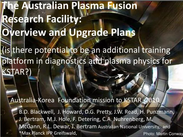
The Australian Plasma Fusion Research Facility: Overview and Upgrade Plans(is there potential to be an additional training platform in diagnostics and plasma physics for KSTAR?) B.D. Blackwell, J. Howard, D.G. Pretty, J.W. Read, H. Punzmann, J. Bertram, M.J. Hole, F. Detering, C.A. Nuhrenberg, M. McGann, R.L. Dewar, J. Bertram Australian National University, and *Max Planck IPP Greifswald, Photo: Martin Conway
The Australian Plasma Fusion Facility: Results and Upgrade Plans Introduction Result Overview: MHD Modes in H-1 Data mining Alfvénic Scaling Optical Measurements Radial Structure Facility Upgrade Aims Key areas New diagnostics for Upgrade Conclusions/Future
H-1NF: the Australian Plasma Fusion Research Facility Originally a Major National Research Facility established by the Commonwealth of Australia and the Australian National University Mission: • Detailed understanding of the basic physics of magnetically confined hot plasma in the HELIAC configuration • Development of advanced plasma measurement systems • Fundamental studies including turbulence and transport in plasma • Contribute to global research effort, maintain Australian presence in the field of plasma fusion power MoU’s for collaboration with Members of the IEA implementing agreement on development of stellarator concept. National Institute of Fusion Science, Princeton Plasma Physics Lab Australian Nuclear Science and Technology Organisation
Major radius 1m • Minor radius 0.1-0.2m • Magnetic Field 1 Tesla (0.2 DC) • q 0.5 -1 (transform 1~2) • ne 1-3x10¹⁸ • Te 20eV (helicon) <200eV (ECH) • 0.01 - 0.1% H-1 CAD
H-1 configuration (shape) is very flexible • “flexible heliac” : helical winding, with helicity matching the plasma, 2:1 range of twist/turn • H-1NF can control 2 out of 3 oftransform () magnetic well and shear (spatial rate of change) • Reversed Shear like Advanced Tokamak mode of operation low shear = 4/3 twist per turn (transform) = 5/4 medium shear Edge Centre
Large Device Physics on H-1 D3D tokamak H-1 Confinement Transitions, Turbulence (Shats… 1996--) • H-mode 1996 • Zonal Flows 2001 • Spectral condensation of turbulence 2005 Magnetic Island Studies • H-1 has flexible, controlled and verified geometry • Create islands in desired locations (shear, transform) • Langmuir probes can map in detail Alfvén Eigenmodes (next )
Santhosh Kumar Experimental confirmation of configurations Rotating wire array • 64 Mo wires (200um) • 90 - 1440 angles High accuracy (0.5mm) Moderate image quality Always available Excellent agreement with computation T.A. Santhosh Kumar B.D.Blackwell, J.Howard Iota ~ 1.4 (7/5)
Santhosh Kumar Effect of Islands on Plasma • LHD, JT60U results show • Te profile flattened – radial transport high (inside side to outsideside) • But this doesn’t mean that internal transport is high (from the inside to the outside of the island.) • Internal rotational transform is quite low and can complicate experiments • 10 to 100 toroidal transits to circumnavigate island? Conditions: Argon plasma ~10eV Te~ 10 eV, Ti~ 10 eV ∼30-80 eV electron density ∼ 1 × 10¹⁸/m3 nn < neutral fill density ∼ 0.81 × 10¹⁸/m3 ρe ∼ 0.075 mm, ρi ∼35-55 mm νei ∼ 9×10⁵/sec νen ∼ 1.6×10⁵/sec Collision mean free path λei ∼2.5 m, λen ∼8 m
Small, core islands Density peaked near island axis (O-point) Potential negatively peaked there too. Local symmetry about local magnetic axis, but apparently not globally (axis to axis) C B A
Unanswered Questions Issues Remaining: What is the correct analysis for Er? When does the plasma “see/not see” islands” collisionality, i, einternal transform are important What is the most robust indicator of surface number? (p? – varies with ne by a fraction of Te (Boltzmann relation)) “Correct” analysis for Er? If we take the axis at the core core electron root If we assume two axes, then ion root, but field is still large (characteristic of e-root) [Conditions for usual e-root picture (1/, trapped e) not met]
David Pretty MHD/Mirnov fluctuations in H-1
Identification of Alfvén Eigenmodes: ne phase • Coherent mode near iota = 1.4, 26-60kHz, Alfvénic scaling with ne • m number resolved by bean array of Mirnov coils to be 2 or 3. • VAlfvén = B/(o) B/ne • Scaling in ne in time (right) andover various discharges (below) 1/ne ne f 1/ne Critical issue in fusion reactors: D + T He + n VAlfvén~ fusion alpha velocity fusion driven instability!
Identification with Alfvén eigenmodes: k||, iota = 4/3 ota (twist) Why is f so low? - VAlfven~ 5x10⁶ m/s res = k||VA =(m/R0)( - n/m)B/(o) • k|| varies as the angle between magnetic field lines and the wave vector k|| - n/m • iota resonant means k||, 0 Expect Fresto scale with iota Resonant
John Howard, Jesse Read Mode structure via synchronous 2D imaging • Intensified Princeton Instruments camera synchronised with mode • Light imaged for various delays • Averaging/Accumulation is performed by the camera Toroidal Field Coils HelicalConductor
John Howard, Jason Bertram, Matthew Hole Alfvén Eigenmode structure in H-1 Compare cylindrical mode with optical emission measurements Test functions for development of a Bayesian method to fit CAS3D modes to experiment.
John Howard, Jesse Read Mirnov Array 1 Mirnov Array 2 Interferometer RF Antenna First Results from Gas Puff Imaging - true 2D imaging • Intensified Princeton Instruments camera synchronised with mode • Select a small range of toroidal angles with a gas puff (Neon) • Intensity ~ ne • Initial results 2D image without assumptions of rotation, mode number. Gas Puff Viewline
Shaun Haskey Mirnov Array 1 Mirnov Array 220 pickup coils Interferometer RF Antenna 0.2m Third Mirnov Array (Toroidal) • New Toroidal Array • Coils inside a SS thin-wall bellows (LP, E-static shield) • Access to otherwise inaccessible region with • largest signals and • with significant variation in toroidal curvature.
Australian Plasma Fusion Research Facility Upgrade • Australian Government’s “Super Science Package” • Boosted National Collaborative Infrastructure Program using the “Educational Infrastructure Fund” $7M, over 4 years for infrastructure upgrades(no additional funding for research) 2009Australian Budget Papers
Aims of Facility Upgrade Consolidate Facility infrastructure including that required to implement the Australian ITER Forum strategy plan Aim to involve the full spectrum of the ITER Forum activities More specifically: • Improve plasma production/reliability/cleanliness • RF production/heating, ECH heating, baking, gettering, discharge cleaning • Improve diagnostics • Dedicated density interferometers and selected spectral monitors permanently in operation • Increasing opportunities for collaboration • Ideas? • Increasing suitability as a testbed for ITER diagnostics • Access to Divertor – like geometry, island divertor geometry
RF Upgrade RF (7MHz) will be the “workhorse” • Low temperature, density limited by power • Required to initiate electron cyclotron plasma New system doubles power: 2x100kW systems. New movable shielded antenna to complement “bare” antenna (water and gas cooled). Advantages: • (non resonant – Helicon) Very wide range of magnetic fields in Argon • (ion-cyclotron resonant) New system allows magnetic field scan while keeping the resonant layer position constant.e.g. to test Alfven scaling MHD Additional ECH source (10/30kW 14/28GHz) for higher Te
Improved Impurity Control Impurities limit plasma temperature (C, O, Fe, Cu) High temperature (>~100eV) desirable to excite spectral lines relevant to edge plasma and divertors in larger devices. Strategy : Combine - • Glow discharge cleaning for bulk of tank • Pulsed RF discharge cleaning for plasma facing components. • antenna (cooled) and source (2.4GHz) • Low temperature (90C) baking • Gettering – Titanium or Boron (o-carborane) Access Island Divertor Geometry Ashley Gibson “Island Divertor”
Small Linear Satellite Device – Plasma Wall Interaction Diagnostics ne ~ 1019 m-3 P ~ 1MW/m2 Purpose: Testing various plasma wall interaction diagnostic concepts e.g. Doppler spectroscopy, laser interferometry coherence imaging, imaging erosion monitor Features: Much higher power density than H-1 H-1 cleanliness not compromised by material erosion diagnostic tests Simple geometry, good for shorter-term students, simpler projects Shares heating and magnet supplies from H-1 Helicon source Mirror coils Magnetic Mirror/ Helicon chamber Optical Diagnostics
Helicon H+ source Concept Based on ANU, ORNL work Gas Flow Water cooled target ne ~ 1019 m-3 m=+1 Helicon Antenna Directional Quartz/ceramic tube • Helicon Antenna is an efficient plasma source in Ar • High Density (>1018 m-3) more difficult in H • Combination of higher power and non-uniform magnetic field has produced ne ~ 1019 m-3in H Mirror Coils (Mirror coils at one end should be sufficient – mainly to provide field gradient rather than full mirror effect.)
Additional Power/Plasma Sources Sheath acceleration increases power density, but if >30-50V physical sputtering (not normal in fusion simulators, but may be useful to increase erosion?) E-beam can increase dissipation, but ion bombardment damage of LaB6 cathode if pressure too high?Solid LaB6 Cathode, >10A emission Sterling Scientific washer gun H+ 1019-1020 5-15eVunder the right conditions, can generatea relatively clean plasma (low W)den Hartog: Plasma Sources Sci. Technol. 6 (1997) 492–498. (also useful for a simple way of obtainingfirst plasma) 15mm
Future Research • New Toroidal Mirnov Array • Bayesian MHD Mode Analysis • Toroidal visible light imaging (Neon) • Correlation of multiple visible light, Mirnov and n~ e data • Spatial and Hybrid Spatial/Temporal Coherence Imaging Facility upgrade • Develop divertor and edge diagnostics • Study stellarator divertors, baffles e.g. 6/5 island divertor • Develop “plasma wall interaction” diagnostics • Linear “Satellite” device for materials diagnostic development multiple plasma sources, approach ITER edge Blackwell, H1 Results & Upgrade, AKF_KSTAR 2010
H-1NF is an excellent toroidal graduate student machine – complements Korean facilities • Large device physics accessible • MHD/Alfvénic modes. • Island studies • Very good diagnostic access • Invites imaging and multiview interferometric diagnostics • Precise control of magnetic geometry, q (0.5 1) and shear. • High repetition rate, availability • 0.5 Tesla : 200 shots/day (hydrogen/helium/deuterium) • Low field student mode : 500 shots/day (argon, Langmuir probes etc.) • Complementary high density hydrogen linear machine (~1019) • Simpler geometry • Edge plasma density and power density approaching ITER (over a small area) • fast diagnostic/vacuum “turnaround” time • MDSPlus/JavaScope data common between KSTAR/H-1NF/MDF