Download
1 / 19
210 likes | 353 Views
PEEM III Endstation Design Review. Endstation Layout Support System Vessel Magnetic Shielding. PEEM III Endstation Design Review. Endstation Layout – Sector 11. PEEM III Endstation Design Review. Endstation Layout. PEEM III Endstation Design Review. Sample Prep and transfer

E N D
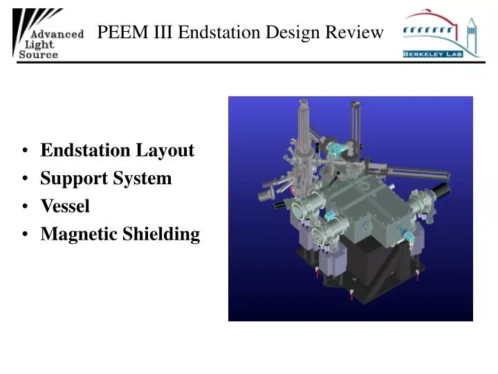
PEEM III Endstation Design Review • Endstation Layout • Support System • Vessel • Magnetic Shielding
PEEM III Endstation Design Review Endstation Layout – Sector 11
PEEM III Endstation Design Review Endstation Layout
PEEM III Endstation Design Review Sample Prep and transfer General HV – UHV in Sample and Mirror Sections < 2x10⁻⁷ Gauss AC Field Nanometer Scale Stability-Sample to Optics “Easy” access to internal components Microscope
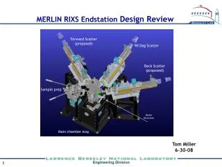
PEEM III Endstation Design Review Microscope - Details Fiber-Optic Laser Separator Replacement Optics Internal Support 5-Axis Sample Manipulator UHV Sub-Chamber 90 degree Optics and Mirror CCD Cameras
PEEM III Endstation Design Review Support System • High stiffness - vibration isolated internal support • Semi-kinematic mounting • Epoxy-granite filled base • Visco-elastic damping • Isolated chamber and external components
PEEM III Endstation Design Review • Install/Align base stand with visco-elastic damping pads • Install/align filled base • Side mounting pads for jacks/ball plates • Mount internal table support legs and align fiducialized table (or plate) • Install/align struts and chamber Support System - Assembly
PEEM III Endstation Design Review Vacuum Vessel
PEEM III Endstation Design Review Vacuum Vessel - Details HV required – UHV desirable SS plate weldment Differentially pumped, double o-ring, window frame to lid seal “Standard” conflat ports
PEEM III Endstation Design Review UHV Sub-Chamber - Details • Aluminum conductance limited UHV-HV sub-chambers • O-Ring base/lid seal • Glass viewing window • Be-Cu sheet interface
PEEM III Endstation Design Review UHV Sub-Chamber - Details
Table 5. Gas loading on the Main Peem3 chamber and pressure after 100 hours with 10" OD tee pumping system, 800 l/s ion pump + 1000 l/s turbo
Schematic arrangement of Peem3 pumping for UHV sub-section and main tank Main Pumping Tee Cu/Be rolled sheet Hole for electrons Main Pumping Adaptor Mu metal Stove Pipe UHV Pump Tee Turbo UHV sub- chamber Window Valve UHV Pump bellows Main Pumping Bellows Ion Pump 2 Main microscope tank Ion Pump 1
Table 7. Gas loading on the UHV sub-chamber and pressure after 100 hours with 8" OD tee pumping system and 800 l/s ion pump. Pressure in main tank = 8.5e-8 torr.
PEEM III Endstation Design Review Magnetic Shielding
Magnetic Shielding requirements • require < 2x10⁻⁷ GaussAC • AC field on the floor of +-0.3mGauss (1Hz) • Need attenuation of ~ 2500 • Crude cylinder model indicate • 2 layers attenuate ~1600 • 3 layers attenuate ~ 26000 • Better calculation by Amuneal suggest • 3 layer attenuation ~ 7000 • Thickness of shield = 3mm for mechanical rigidity • Shield spacing = 25mm – as large as possible • given space constrains • Degaussing of inner shield with AC and internal coils Magnetic field at Peem3 location Model of mu metal shields with Vacuum chamber removed
PEEM III Endstation Design Review Magnetic Shielding 3 Concentric boxes with ~ 1’’ gap Assembled from outside – in Separated with aluminum spacers/handle mounts PEM fasteners @ ~3.5” spacing No penetrations > 5 diameters in critical areas - tubulations ~ 3 diameters in 2 pump sections
PEEM III Endstation Design Review Tubulation Details Magnetic Shielding
PEEM III Endstation Design Review The End(Hopefully)