Download
1 / 50

E N D
Gear box: Necessity for gear ratios in transmission, Synchronous gear boxes, 3, 4 and 5 speed gear boxes, Free Wheeling mechanism, Planetary gears systems, over drives, fluid coupling and torque converters, Epicyclic gear box, principle of automatic transmission, calculation of gear ratios
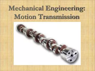
Automotive Gears: Gears play an important role in trucks, car, buses, motor bikes and even geared cycles. These gears control speed and include gears like ring and pinion, spiral gear, hypoid gear, hydraulic gears, reduction gearbox.
Depending on the size of the vehicles, the size of the gears also varies. There are low gears covering a shorter distance and are useful when speed is low. There are high gears also with larger number of teeth.
Functions of Transmission To provide the high torque at the time of starting, hill climbing, accelerating and pulling a load since high tractive effort is needed It permits engine crankshaft to revolve at high speed, while the wheels turn at slower speeds Variable torque by set of gears Vehicle speed can be changed keeping engine speed same with certain limit
The transmission also provides a neutral position so that the engine and the road wheels are disconnected even with the clutch in the engaged position A means to back the car by reversing the direction of rotation of the drive is also provided by the transmission
Necessity of transmission Variation of resistance to the vehicle motion at various speeds Variation of tractive effort of the vehicle available at various speeds
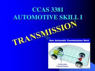
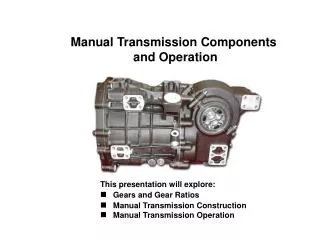
Types of Transmission • Manual Transmission • Sliding Mesh Gear box • Constant Mesh Gear box • Synchromesh Gear box • Automatic Transmission • Over drive (semi-automatic) • Fluid drive or Fluid coupling • Fully automatic • Epicyclic gear box • Free Wheeling unit • Torque Convertor
Fluid Coupling or Torque Convertor A fluid coupling is a hydrodynamic device used to transmit rotating mechanical power. It has been used in automobile transmission as an alternative to a mechanical clutch
Fluid coupling consists of three components, plus the hydraulic fluid: • The housing, also known as the shell(which must have an oil tight seal around the drive shafts), contains the fluid and turbines. • Two turbines: • One connected to the input shaft; known as the pump or impellor,primary wheel,input turbine, driving member • The other connected to the output shaft, known as the turbine, output turbine, secondary wheel or runner or driven member
The driving turbine, known as the 'pump', (or driving torus) is rotated by the prime mover, which is typically an internal combustion engine or electric motor. The impellor's motion imparts both outwards linear and rotational motion to the fluid. The hydraulic fluid is directed by the 'pump' whose shape forces the flow in the direction of the 'output turbine' (or driven torus). Here, any difference in the angular velocities of 'input stage' and 'output stage' result in a net force on the 'output turbine' causing a torque; thus causing it to rotate in the same direction as the pump. The motion of the fluid is effectively toroidal - travelling in one direction on paths that can be visualised as being on the surface of a torus: If there is a difference between input and output angular velocities the motion has a component which is circular (i.e. round the rings formed by sections of the torus) If the input and output stages have identical angular velocities there is no net centripetal force - and the motion of the fluid is circular and co-axial with the axis of rotation (i.e. round the edges of a torus), there is no flow of fluid from one turbine to the other.
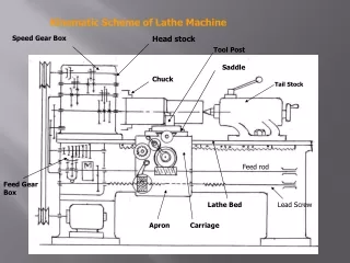
The figure shows the power transmission system of an automobile . The motion of the crank shaft is transmitted through the clutch to the gear box. From the gear box the motion is transmitted to the propeller shaft through the universal joint and then to differential through another universal joint. Finally power transmitted to the rear wheels through the rear axle.