Download
1 / 41
440 likes | 926 Views
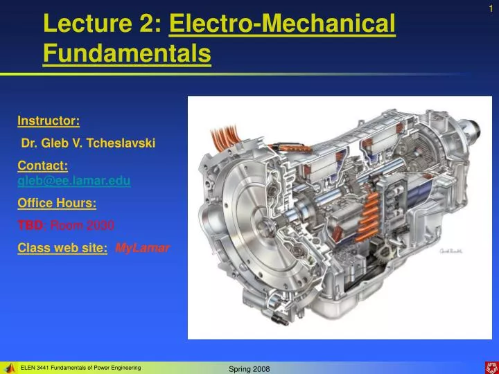
Lecture 2: Electro-Mechanical Fundamentals. Instructor: Dr. Gleb V. Tcheslavski Contact: gleb@ee.lamar.edu Office Hours: TBD ; Room 2030 Class web site: MyLamar. 1. Electric machines and Power Systems.

E N D
Lecture 2: Electro-Mechanical Fundamentals Instructor: Dr. Gleb V. Tcheslavski Contact:gleb@ee.lamar.edu Office Hours: TBD; Room 2030 Class web site:MyLamar
1. Electric machines and Power Systems An electric machine is a devise that can convert electrical energy to mechanical or/and mechanical energy to electrical. A power system is a network of components designed to efficiently transmit and distribute the energy.
1. Electric machines and Power Systems 1.1. Generators convert mechanical energy from a prime mover to electrical energy through the action of the magnetic field.
1. Electric machines and Power Systems 1.2. Transformers convert AC electrical energy at one voltage level to AC electrical energy at (an)other voltage level(s).
1. Electric machines and Power Systems 1.3. Power lines connect generators to loads transmitting electrical power over long distance with minimal losses. There are two categories: transmission lines and distribution lines.
1. Electric machines and Power Systems 1.4. Loads are all types of electricity consuming devises: motors, electric lighting, computers, TVs, phones…
1. Electric machines and Power Systems 1.5. Protective devices: current, voltage, power sensors, relays, fuses, circuit breakers.
2. Rotational motion, Newton’s law Majority of electric machines rotate about an axis called a shaft of the machine. 2.1. Angular position - an angle at which the object is oriented with respect to an arbitrary reference point. 2.2. Angular velocity (speed) - a rate of change of the angular position. (2.8.1) m – angular velocity in radians per second fm – angular velocity in revolutions per second nm – angular velocity in revolutions per minute (2.8.2) (2.8.3)
2. Rotational motion, Newton’s law 2.3. Angular acceleration - a rate of change of angular velocity. (2.9.1) 2.4. Torque (moment) - a “rotating force”. axis (2.9.2) Here F is an acting force, r is the vector pointing from the axis of rotation to the point where the force is applied, is the angle between two vectors. r F Newton’s law of rotation: (2.9.3) J is a moment of inertia (a mass equivalent).
2. Rotational motion, Newton’s law 2.5. Work W – amount of energy transferred by a force. (2.10.1) If the torque is constant: (2.10.2) 2.6. Power P – increase in work per unit time. (2.10.3) For a constant torque: (2.10.4)
3. The magnetic field Basic principles underlying usage of magnetic field • A wire caring a current produces a magnetic field around it. • A time-changing magnetic field induces a voltage in a coil of wire if it passes through that coil (transformer action). • A wire caring a current in the presence of a magnetic field experiences a force induced on it (motor action). • A wire moving in a presence of a magnetic field gets a voltage induced in it (generator action).
3. The magnetic field 3.1. Production of magnetic field The Ampere’s law: (2.12.1) Where H [A-turns/m] is the intensity of the magnetic field produced by the current Inet For the ferromagnetic cores, almost all the magnetic field produced by the current remains inside the core, therefore the integration path would be lc and the current passes it N times. (2.12.2)
3. The magnetic field Magnetic flux density: (2.13.1) where is the magnetic permeability of a material. r – the relative permeability The total flux in a given area: (2.13.2) If the magnetic flux density vector B is perpendicular to a plane of the area: (2.13.3)
3. The magnetic field 3.2. Magnetic circuits Similarly to electric circuits, there are magnetic circuits … Instead of electromotive force (voltage) magnetomotive force (mmf) is what drives magnetic circuits. (2.14.1) Direction of mmf is determined by RHR… Like the Ohm’s law, the Hopkinson’s Law: (2.14.2)
Permeance: Magnetic flux: Therefore, the reluctance: Serial connection: Parallel connection: 3. The magnetic field (2.15.1) (2.15.2) (2.15.3) (2.15.4) (2.15.5)
3. The magnetic field Calculations of magnetic flux are always approximations! • We assume that all flux is confined within the magnetic core but a leakage flux exists outside the core since permeability of air is non-zero! • A mean path length and cross-sectional area are assumed… • In ferromagnetic materials, the permeability varies with the flux. • In air gaps, the cross-sectional area is bigger due to the fringing effect.
3. The magnetic field Example 1: A ferromagnetic core with a mean path length of 40 cm, an air gap of 0.05 cm, a cross-section 12 cm2, and r = 4000 has a coil of wire with 400 turns. Assume that fringing in the air gap increases the cross-sectional area of the gap by 5%, find (a) the total reluctance of the system (core and gap), (b) the current required to produce a flux density of 0.5 T in the gap. The equivalent circuit
3. The magnetic field (a) The reluctance of the core: Since the effective area of the air gap is 1.05 x 12 = 12.6 cm2, its reluctance: The total reluctance: The air gap contribute most of the reluctance!
3. The magnetic field (b) The mmf: Therefore: Since the air gap flux was required, the effective area of the gap was used.
3. The magnetic field Example 2: In a simplified rotor and stator motor, the mean path length of the stator is 50 cm, its cross-sectional area is 12 cm2, and r = 2000. The mean path length of the rotor is 5 cm and its cross-sectional area is also 12 cm2, and r = 2000. Each air gap is 0.05 cm wide, and the cross-section of each gap (including fringing) is 14 cm2. The coil has 200 turns of wire. If the current in the wire is 1A, what will the resulting flux density in the air gaps be? The equivalent circuit
3. The magnetic field The reluctance of the stator is: The reluctance of the rotor is: The reluctance of each gap is: The total reluctance is:
3. The magnetic field The net mmf is: The magnetic flux in the core is: Finally, the magnetic flux density in the gap is:
3. The magnetic field 3.3. Magnetic behavior of ferromagnetic materials Magnetic permeability can be defined as: (2.23.1) and was previously assumed as constant. However, for the ferromagnetic materials (for which permeability can be up to 6000 times the permeability of air), permeability is not a constant… A saturation (magnetization) curve for a DC source
3. The magnetic field The magnetizing intensity is: (2.24.1) The magnetic flux density: (2.24.2) Therefore, the magnetizing intensity is directly proportional to mmf and the magnetic flux density is directly proportional to magnetic flux for any magnetic core. Ferromagnetic materials are essential since they allow to produce much more flux for the given mmf than when air is used.
3. The magnetic field 3.4. Energy losses in a ferromagnetic core If instead of a DC, a sinusoidal current is applied to a magnetic core, a hysteresis loop will be observed… If a large mmf is applied to a core and then removed, the flux in a core does not go to zero! A magnetic field (or flux), called the residual field (or flux), will be left in the material. To force the flux to zero, an amount of mmg (coercive mmf) is needed.
3. The magnetic field Ferromagnetic materials consist of small domains, within which magnetic moments of atoms are aligned. However, magnetic moments of domains are oriented randomly. When an external magnetic field is applied, the domains pointing in the direction of that field grow since the atoms at their boundaries physically switch their orientation and align themselves in the direction of magnetic field. This increases magnetic flux in the material which, in turn, causes more atoms to change orientation. As the strength of the external field increases, more domains change orientation until almost all atoms and domains are aligned with the field. Further increase in mmf can cause only the same flux increase as it would be in a vacuum. This is a saturation.
3. The magnetic field When the external field is removed, the domains do not completely randomize again. Realigning the atoms would require energy! Initially, such energy was provided by the external field. Atoms can be realigned by an external mmf in other direction, mechanical shock, or heating. The hysteresis loss in the core is the energy required to reorient domains during each cycle of AC applied to the core. Another type of energy losses is an eddy currents loss, which will be examined later.
4. The Faradays law If a flux passes through a turn of a coil of wire, a voltage will be induced in that turn that is directly proportional to the rate of change in the flux with respect to time: (2.28.1) Or, for a coil having N turns: (2.28.2) eind – voltage induced in the coil N – number of turns of wire in the coil - magnetic flux passing through the coil
4. The Faradays law The “minus” sign in the equation is a consequence of the Lentz’s law stating that the direction of the voltage buildup in the coil is such that if the coil terminals were short circuited, it would produce a current that would cause a flux opposing the original flux change. If the initial flux is increasing, the voltage buildup in the coil will tend to establish a flux that will oppose the increase. Therefore, a current will flow as indicated and the polarity of the induced voltage can be determined. The minus sign is frequently omitted since the polarity is easy to figure out.
4. The Faradays law The equation (2.28.2) assumes that the same flux is passing through each turn of the coil. If the windings are closely coupled, this assumption almost holds. In most cases, a flux leakage occurs. Therefore, more accurately: (2.30.1) (2.30.2) (2.30.3) - a flux linkage of the coil: (2.30.4)
4. The Faradays law A nature of eddy current losses: Voltages are generated within a ferromagnetic core by a time-changing magnetic flux same way as they are induced in a wire. These voltages cause currents flowing in the resistive material (ferromagnetic core) called eddy currents. Therefore, energy is dissipated by these currents in the form of heat. The amount of energy lost to eddy currents is proportional to the size of the paths they travel within the core. Therefore, ferromagnetic cores are frequently laminated: core consists of a set of tiny isolated strips. Eddy current losses are proportional to the square of the lamination thickness.
5. Production of induced force on a wire A second major effect of a magnetic field is that it induces a force on a wire caring a current within the field. (2.32.1) Where I is a vector of current, B is the magnetic flux density vector. For a wire of length l caring a current i in a magnetic field with a flux density B that makes an angle to the wire, the magnitude of the force is: (2.32.2) This is a basis for a motor action.
6. Induced voltage on a conductor moving in a magnetic field The third way in which a magnetic field interacts with its surrounding is by an induction of voltage in the wire with the proper orientation moving through a magnetic field. (2.33.1) Where v is the velocity of the wire, l is its length in the magnetic field, B – the magnetic flux density This is a basis for a generator action.
7. Real, reactive, and apparent power In a DC circuit, the power is: (2.34.1) In an AC circuit, an instantaneous power is a product of an instantaneous voltage and an instantaneous current. The voltage applied to an AC load is: (2.34.2) Where V is the root mean square (rms) value of a voltage applied to the load.
7. Real, reactive, and apparent power The current flowing through the AC load will be (2.35.1) Where I is an rms value of the current and is the impedance angle. Therefore, the instantaneous power will be: (2.35.2) For inductive loads, is positive and the current lags the voltage. (2.35.3)
7. Real, reactive, and apparent power The first component of (2.35.3) is in phase with the voltage while the second term is due to the current that is 900 out of phase. The average value of the first term is the average or real power: (2.36.1) The average power supplied by the second term is zero. The second term represents an reactive power: power that is transmitted to the load and then reflected back to the power source either through electric energy stored in a capacitor or through magnetic energy stored in an inductor.
7. Real, reactive, and apparent power The reactive power of a load is given by: (2.37.1) By the convention, Q is positive for inductive loads and negative for capacitive loads. Units are volt-amperes reactive (var). The power that “appears” to be supplied to the load is called the apparent power: (2.37.2)
7. Real, reactive, and apparent power 7.1. Alternative forms of power equations The magnitude of voltage across the load Z is: (2.38.1) Therefore: (2.38.2) (2.38.3) reactance Z is the magnitude of the impedance Since the impedance of the load Z is (2.38.4) (2.38.5) (2.38.6)
7. Real, reactive, and apparent power 7.2. Complex power For a simplicity of computer calculations, real and reactive power are sometimes represented together as a complex power S: (2.39.1) and denote: (2.39.2)
7. Real, reactive, and apparent power 7.3. The relationship between impedance angle, current angle, and power (2.40.1) If the impedance angle of the load is positive, the phase angle of the current flowing through the load will lag the phase angle of voltage. Inductive load If the impedance angle is positive, the load is said to consume both real and reactive power from the source (the reactive power is positive) Capacitive loads have a negative impedance angle and are said to consume real power and supply reactive power to the source. Capacitive load
7. Real, reactive, and apparent power 7.3. The power triangle The real, reactive, and apparent power supplied to a load are related by the power triangle. cos is usually called a power factor of the load: (2.41.1) Since the sign of the impedance angle does not affect the PF, it is usually specified whether the current is leading or lagging the voltage.