Download
1 / 27
270 likes | 276 Views
Experimental Study of NOMA/SOMA in Wi-Fi. Authors:. Date: 2019-03-11. Outline. Motivation NOMA and SOMA brief introduction KPIs Theoretical results Testbed description November’18 results for NOMA (and short links) February’19 results for SOMA (and long links). Motivation.

E N D
Experimental Study of NOMA/SOMA in Wi-Fi Authors: Date: 2019-03-11 Evgeny Khorov (IITP RAS)
Outline Motivation NOMA and SOMA brief introduction KPIs Theoretical results Testbed description November’18 results for NOMA (and short links) February’19 results for SOMA (and long links) Evgeny Khorov (IITP RAS)
Motivation In current networks, it is a typical situation when an AP serves several devices located at different distances from the AP (thus having different channel attenuation) having different traffic load. In this case, Non-orthogonal multiple access (NOMA) can be a promising solution to increase spectrum efficiency. This presentation considers theoretical and experimental results for DOWNLINK NOMA. [1] proposes SOMA, which is actually a specific case of NOMA (having no SIC). [1] doc.: IEEE 802.11-18/1462r0 SOMA for EHT Evgeny Khorov (IITP RAS)
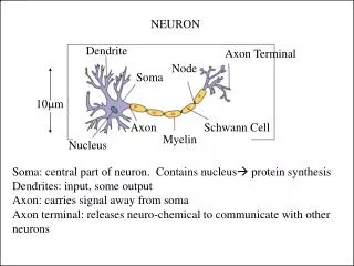
Basic Idea of Downlink NOMA Different MCSs NOMA Traditional TDMA STA 2 AP Power Power P P To STA1 To STA2 To STA2 STA2 decodes signal to STA1 and performs Successive Interference Cancelation (SIC) To STA1 STA 1 Evgeny Khorov (IITP RAS)
Signal Superposition TX side RX side STA2 STA1 Q Evgeny Khorov (IITP RAS) I
A possible transmission process SIFS SIFS DIFS To STA2 To STA1 AP STA1 ACK STA2 ACK Evgeny Khorov (IITP RAS)
With SOMA, no SIC is needed STA 1 STA 2 STA 2 AP 0001 0011 1011 1001 0000 0010 1010 1000 0100 1110 0110 1100 Gray-mapped superposed constellation 0101 1111 0111 1101 STA 1 Result BPSK QPSK Q Q Q Q Can be considered as multiplexing + reflection of constellations I I I I
KPI • Average throughput • Can be increased if we block the client with the worst channel conditions • Geometric Mean Throughput • KPI, widely used in cellular networks optimization as the target utility function: • Equals zero, if any client is blocked • Reaches the maximum value, if all the clients share the channel fairly (the same portion of channel time) • This is called proportional fair resource allocation • In a scenario with N client (saturated/full buffer/ traffic), each client obtains throughput where T is the maximal throughput if the client is alone. Evgeny Khorov (IITP RAS)
Theoretical Results for 11a Payload 1K/4K to align NOMA payloads Comments Round Robin 1K/1K – Equal throughput for both STAs Round Robin 1K/4K – Throughput for STA1 goes down, Throughput for STA2 is 4 times higher than for STA1 Proportional fair 1K/4K – Equal channel time. Thrp for STA1 even lower, Thrp for STA 2 even higher -> Max Geomeric Mean Thrp NOMA 1K/4K – 92% gain in thrp for STA1, small gain in thrp for STA2, Overall gain +43% Evgeny Khorov (IITP RAS)
Trade-off between throughputs for STA1 & STA2 max average/total thrp is not a good target Proportional fair operation point =0.85 Mix of NOMA (STA1 and STA2) and CSMA (STA2) Round Robin Operation point Evgeny Khorov (IITP RAS)
Testbed AP (SDR) Can be used with legacy off-the-shelf device! STA2(SDR) As NOMA device STA1(Laptop) legacy device Full description: E. Khorov, A. Kureev, I. Levitsky. NOMA Testbed on Wi-Fi. //In Proc. of IEEE PIMRC, Bologna, Italy, 9-12 September 2018 Evgeny Khorov (IITP RAS)
TX Implementation Source TX IQ Processing Data bytes to bits Encoder Modulator Data 1 FFT to RF Encoder Modulator Data bytes to bits Data 2 +reflection
RX Implementation • Demodulator & Decoder • Destination • Bits to • data bytes • Demodulator • Decoder Data 1 RX IQ Processing from RF • Bits to • data bytes • Demodulaor • Decoder Data 2 weak signal is isolated here Always trying to separate SOMA packets If no SOMA, the following check fails: Reserved bit, tail bits, parity bits, N_SYM1 ≥ N_SYM2 (NO additional “SOMA indication bits” used!)
Implementation PHY RX State machine for weak signal False Reserved bit, tail bits, parity check passed & N_SYM1 ≥ N_SYM2 L-SIG decoding Signal detected IDLE Done True False extracted FCS check passed Frame decoding Done True Frame received
Capabilities IE • Indicator that a device is able to decode a NOMA/SOMA frame • the other of NOMA/SOMA (optional) • The way how modulations are multiplexed • For example, Gray-mapped superposed constellation Minimal set of changes to the standard
November results Evgeny Khorov (IITP RAS)
Testbed. Experimental Setup AP (SDR) A legacy device is replaced with SDR to simplify gathering statistics STA2(SDR) As NOMA device In November experiments, we located devices in the same room, reduced TX power and used 30dB attenuators to model different channel conditions STA1(SDR) As legacy device Evgeny Khorov (IITP RAS)
Evaluation. Reference Throughputs STA1 Payload ~ 1kB STA2 Payload ~ 2kB Different payloads are needed to make multiplexed frames of the same duration Evgeny Khorov (IITP RAS)
Testbed. Results NOMA Link1 MCS1 Link2 MCS3 STA1 Payload ~ 1kB STA2 Payload ~ 2kB x1.5 Obtained as the average throughput of STA 1 and STA2, when each of them has 50% of channel time Evgeny Khorov (IITP RAS)
Balance between throughput for STA1 & STA2 =0.86 Mix of NOMA (STA1 and STA2) and CSMA (STA2) Evgeny Khorov (IITP RAS)
February results (SOMA) Evgeny Khorov (IITP RAS)
Testbed. Experimental Setup AP (SDR) STA2(SDR) As NOMA device STA1(SDR) As legacy device In February experiments, we located devices in separate rooms to provide different channel conditions for STA1 and STA2. Evgeny Khorov (IITP RAS)
Location of devices (AP) STA1 Now, the devices are located in different rooms and no attenuators are used STA2 Evgeny Khorov (IITP RAS)
Example of stats Evgeny Khorov (IITP RAS)
Testbed Results PF Link1 MCS1 Link2 MCS5 SOMA Link1 MCS1 Link2 MCS3 Twice lower because of fair sharing x1.4 Evgeny Khorov (IITP RAS)
NOMA/SOMA Properties • Backward compatibility (STA 1 can be legacy) • Even if not standardized, any vendor can use NOMA/SOMA for transmission between its own devices, and at the same time transmit data to other devices. • Almost double throughput for the STA with poor channel (in case of fare resource allocation) OR • Manifold gain in throughput of the nearest STA (STA 2) while providing guaranteed throughput for the far STA (STA 1) Evgeny Khorov (IITP RAS)
Straw Poll Should NOMA/SOMA be supported by EHT? Yes No Need more info Abstain Evgeny Khorov (IITP RAS)