Download
1 / 10
100 likes | 112 Views
System Capacity Evaluation in OBSS Environment at 5 GHz band. Date: 2010-11-08. Authors:. TGac agreed that inter-cell interference (ICI) in overlapping BSSs (OBSSs) environment is regarded as one of the main topics in coexistence ad-hoc group scope [1], [2].

E N D
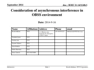
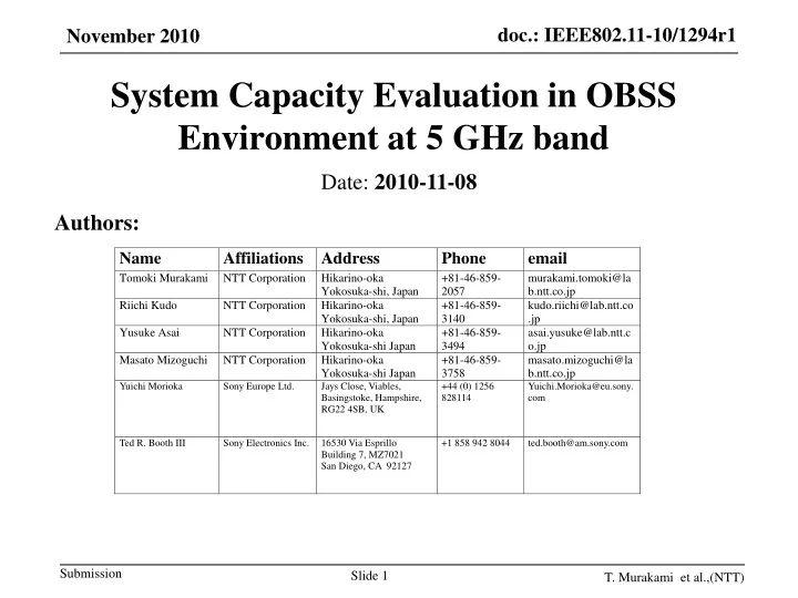
System Capacity Evaluation in OBSS Environment at 5 GHz band Date: 2010-11-08 Authors: T. Murakami et al.,(NTT)
TGac agreed that inter-cell interference (ICI) in overlapping BSSs (OBSSs) environment is regarded as one of the main topics in coexistence ad-hoc group scope [1], [2]. The number of OBSSs will increase in the future. TGac has already agreed to support 80 / 160MHz modes, which results in decrease the number of available channels [3], [4]. The number of APs and STAs supporting 11ac function will increase. The objective of our research is to discover potential of each bandwidth modes in terms of system capacity on PHY layer against BSS density. Background T. Murakami et al.,(NTT)
OBSS simulation model(1/2) • We evaluate system capacity per square meter against BSS density to consider influence of ICI. • Channelization for Europe and Japan operation in11ac • Communication area *Total transmit power is constant BSS • Communication area • This area is defined by carrier sense level of each bandwidth modes. AP Downlink STA T. Murakami et al.,(NTT)
OBSS simulation model (2/2) • BSS density D is defined by number of BSSs per square meter few many Number of BSSs per square meter Low High BSS density D T. Murakami et al.,(NTT)
Simulation process • Locate each BSS randomly. • The number of BSS corresponds to BSS density D. • Assign channel number to each BSS at random. • All BSSs use common bandwidth mode. • Each BSS tries to communicate: • If overlapping BSSs exist, only one AP can communicate to its STA. The other APs defer to communicate. • Non-overlapping BSSs can communicate at the same time. • Calculate capacity of the center BSS. T. Murakami et al.,(NTT)
Simulation conditions Slide 6 T. Murakami et al.,(NTT)
Calculation • Calculation formula of system capacity per square meter Cis as follows: B: bandwidth [MHz] D: BSS density [number/m2] N: number of iterations Nsub: number of sub-carriers Nfft: number of FFT points K: number of active BSSs except center BSS When a BSS transmits data atn-th iteration, its instantaneous capacity is: Element of ICI Otherwise: T. Murakami et al.,(NTT)
System capacity vs. BSS density Large house Family apartment Small apartment • As BSS density becomes higher, effectiveness of allocating wider bandwidth mode becomes lower. • This is because ICI from OBSSs increases. • In average Japanese apartment environment [6], 40 MHz mode is the best choice (D = 1/48m2.) • At low BSS density, system capacity of 160MHz is the best. • However, 160 MHz capacity is only 1.3 times that of 80 MHz although twice the bandwidth is used, because transmit power per sub-carrier becomes lower as bandwidth expands. Low density High density 1/200m2 1/100m2 1/50m2 T. Murakami et al.,(NTT)
Summary • We evaluated system capacity per square meter on PHY layer against BSS density, assuming the current bandwidth modes (20, 40, 80, and 160 MHz). • We found that capacity for wider bandwidth mode at high BSS density becomes lower because ICI from OBSSs increases. • Also, we found that the wider bandwidth mode is allocated, the higher system capacity is achieved at low BSS density. • These results suggests that TGac should carefully specify the use wide bandwidth mode especially when BSS density is high. T. Murakami et al.,(NTT)
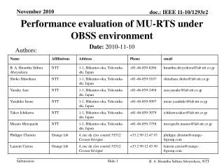
References • [1]Rolf de Vegt et al., “Proposed Scope for Tgac Ad Hoc Groups,” Doc.: IEEE 802.11-09/1175r1. • [2] T. Takatori et al., “OBSS issue in 802.11ac,” Doc.: IEEE 802.11-09/0536r0. • [3] L. Cariou et al., “Evaluation of the saturation of the 5GHz band,” Doc.: IEEE 802.11-10/0846r2. • [4] R. Stacey et al., “Specification Framework for TGac,” Doc.: IEEE 802.11-09/0992r15. • [5] G. Smith, “TGaa OBSS background,” Doc.: IEEE 802.11-09/0762r0. • [6] B. A. H. S. Abeysekera et al., “Performance evaluation of MU-RTS under OBSS environment,” Doc.: IEEE 802.11-10/????r0. Slide 10 T. Murakami et al.,(NTT)