Download
1 / 21
260 likes | 479 Views
EYE BALL CONTROLLED AUTOMATIC WHEEL CHAIR FOR PARALYSED PATIENTS. PREPARED BY : -RIDDHI G. SANGHANI(100160111013 ) -ASHA C. SAKARIYA(100160111045). ABSTRACT.

E N D
EYE BALL CONTROLLED AUTOMATIC WHEEL CHAIR FOR PARALYSED PATIENTS PREPARED BY: -RIDDHI G. SANGHANI(100160111013) -ASHA C. SAKARIYA(100160111045)
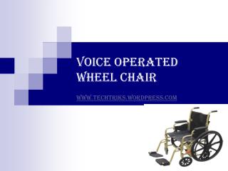
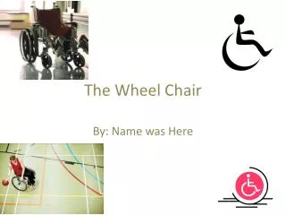
ABSTRACT Wireless intellichair is designed to help the paralysed person who moves on a wheel chair, instead of the handicapped person moves the wheel chair by his hand, the chair will automatically move to a particular direction as the patient moves his eyes towards a direction, with the help of Eye ball movement detection sensor. The chair will also sense the obstacles in front of it and gives a beep sound.
MOTIVATION The numbers of persons who are paralyzed dependent on others due to loss of self-mobility is growing as the population ages. We have developed a wheelchair prototype exclusively controlled by eye and able to be used different users while proving robust against vibration, illumination change, and user movement. The keys to this flexibility are the camera mounted on the user’s glasses and the use of pupil detection. Image processing analyzes the user’s gaze for wheelchair control.
Power Supply Ultrasonic Sensor AVR Microcontroller Board DC Motor
DESCRIPTION OF BLOCK DIAGRAM • AVR Microcontroller Board: This is the board which contains AVR Microcontroller Chip as well as the clock Circuitry, Reset Circuit and Power Supply for the Microcontroller. • Power supply: Provides Power Supply for the IC’s and components • Intruder Sensor An Infrared sensor is used as a intruder detector. So when an intruder is sensed we can redirect the movement of the Model. • Eye ball Movement Sensor: This is used to sense the movement of the eye ball’s direction and converts it into digital data and transfers it to the Master controller. (Straight Command, Left/Right Command, Stop Command)
HARDWARE REQUIREMENTS • AVR Controller • Eye ball Movement Sensor • Infrared Sensor • Ultrasonic sensor • DC Motor
AVR MICROCONTROLLER • The AVR is a modified Harvard architecture 8-bit RISC single chip microcontroller which was developed by Atmel in 1996. The AVR was one of the first microcontroller families to use on-chip flash memory for program storage. It is a machine where program and data are stored in separate physical memory systems that appear in different address spaces, but having the ability to read data items from program memory using special instructions. AVRs are generally classified into following: • tinyAVR — the AT tiny series • megaAVR — the ATmega series • XMEGA — the AT xmega series
Program instructions are stored in non-volatile flash memory. • The data address space consists of the register files, I/O registers, and SRAM. • The AVRs have 32 single-byte registers and are classified as 8-bit RISC devices • Each port consists of three registers: DDRx, PORTx and PINx. • all AVR microcontrollers have internal EEPROM for semi-permanent data storage. • Atmel's AVRs have a two stage, single level pipeline design. This means the next machine instruction is fetched as the current one is executing.
FEATURES • Multifunction, bi-directional general-purpose I/O ports with configurable, built-in pull-up resistors • Multiple internal oscillators, including RC oscillator without external parts • Internal, self-programmable instruction flash memory up to 256 kB • Internal data EEPROMup to 4 kB • Internal SRAM up to 16 kB • 8-bit and 16-bit timers • Analog comparator • 10 or 12-bit A/D converters, with multiplex of up to 16 channels • 12-bit D/A converters • CAN controller support • USB controller support • Ethernet controller support • LCD controller support
Principle of eye ball sensor • The basic principle of this direction sensing is the colour of the eyes. There are two main colour pigments in the human eyes. i.e., black and white. The colours show different wavelengths in the spectrum. White being the farthest colour in emits the lowest wavelength. So the wavelength of white light is chosen as the standard parameter. White light can be measured by infrared sensors. • The infrared light ray measures and reflects the wavelength emitted by the white portion and based on that the eyeball sensor is constructed.
IR SENSOR • An infrared sensor is an electronic device that emits and/or detects infrared radiation in order to sense some aspect of its surroundings. Infrared sensors can measure the heat of an object, as well as detect motion. Many of these types of sensors only measure infrared radiation, rather than emitting it, and thus are known as passive infrared (PIR) sensors.
WORKING PRINCIPLE • IR Sensors work by using a specific light sensor to detect a select light wavelength in the Infra-Red (IR) spectrum. By using an LED which produces light at the same wavelength we get the intensity of the received light. When an object is close to the sensor, the light from the LED bounces off the object and into the light sensor. This results in a large jump in the intensity.
ULTRASONIC SENSOR • Ultrasonic sensor work on a principle similar to radar or sonarwhich evaluate attributes of a target by interpreting the echoes from radio or sound waves respectively. Ultrasonic sensors generate high frequency sound waves and evaluate the echo which is received back by the sensor. Sensors calculate the time interval between sending the signal and receiving the echo to determine the distance to an object.
TIMING DIAGRAM • Supply a short 10uS pulse to the trigger input to start the ranging, and then the module will send out an 8 cycle burst of ultrasound at 40 kHz and raise its echo. The Echo is a distance object that is pulse width and the range in proportion . Range is calculated through the time interval between sending trigger signal and receiving echo signal. • Formula: uS / 58 = centimeters or uS / 148 =inch; or: the range = high level time * velocity (340M/S) / 2.
DC MOTOR • Every DC motor has six basic parts - axle, rotor (armature), stator, commutator, field magnet(s), and brushes. In most common DC motors , the external magnetic field is produced by high-strength permanent magnets. The stator is the stationary part of the motor - this includes the motor casing, as well as two or more permanent magnet pole pieces. The rotor rotate with respect to the stator. The rotor consists of windings the windings is being electrically connected to the commutator.
PRINCIPLE OF OPERATION • In any electric motor, operation is based on simple electromagnetism. A current-carrying conductor generates a magnetic field; when this is then placed in an external magnetic field, it will experience a force proportional to the current in the conductor, and to the strength of the external magnetic field. • The application of motors mainly looks at three aspects of operation. • 1. Starting • 2. Speed control • 3. Braking
ADVANTAGES • It allows user movement: User can move during using the proposed system in directions in the allowable distance of which the camera mounted on the glass acquires user face. • It is robust against immunization changes, additive noises, vibrations to the EWC, user nationality (different colour of eye as well as skin, size, and shape of eye), eyelid influence, and shade and shadow. • Provides self mobility • Using eye ball sensor we can easily calculate the threshold values of position. • Using eye ball sensors instead of the CCD camera will also reduce the cost of the total system.
DISADVANTAGES • the drawback with this project is as the wheel chair requires eye-ball movement as input to the controller for its working, a lot of strain is created to the eyes. • Uses more electricity • Provides no exercise
CONCLUSION • In this project we developed a robotic wheelchair with an in-built programmed microcontroller to which sensors are connected. This microcontroller makes the wheelchair move in straight, left and right directions with the help of motors. This project enables the disabled patients to move their wheelchair in their own directions without the help of any other person. • In the real time application we can use long range ultrasonic for the sensing of obstacles in a little far distance always monitor the position of wheelchair like as it bend and front or back or right or left. Thus this project enables to help the physically challenged persons to move freely with their own control of the wheel chair and that is the sensor based automated wheelchair.