Download
1 / 21
210 likes | 397 Views
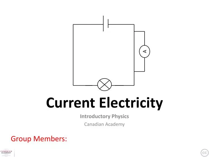
Current Electricity. A. Introductory Physics Canadian Academy. Group Members: . Is this plausible?. Could you really power a house with static electricity?. http:// www.youtube.com / watch?v = scUosAkxlvo. Current Electricity. Construct and explain. .

E N D
Current Electricity A Introductory Physics Canadian Academy Group Members:
Is this plausible? Could you really power a house with static electricity? http://www.youtube.com/watch?v=scUosAkxlvo
Current Electricity Construct and explain. • Work in pairs or by yourself for these tasks. • With each question: • Build it in the PhET simulation • Build it in the lab if possible • Draw the circuit diagram and answer the questions on the slide. • You should be able to: • Define current electricity • Define resistance and state the factors that affect resistance in a metal wire • Define potential difference (voltage) • Explain the effect of potential difference and resistance on a current • Draw basic circuit diagrams involving batteries, lamps, switches and wires • Define electrical power including the relationship to voltage and current http://phet.colorado.edu/en/simulation/circuit-construction-kit-dc Your finished work should be uploaded to SlideShare (or Google Docs if it works) and embedded into a blog post.
Some basic circuit symbols You can use these to build the circuits on the next slides. battery cell wire junction + - + - cathode anode electron flow bulb/ lamp resistor V A conventional current What do these two components measure? switch voltmeter ammeter Voltmeter measures the potential difference in charge between two points on a circuit, while ammeter is used to measure the electrical current of a circuit.
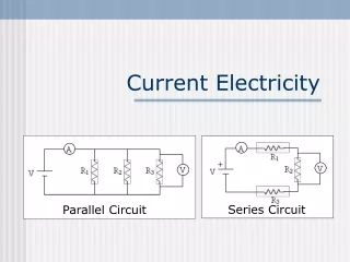
A simple series circuit • Define current electricity. • It is a flow of electrons/electrical charge and can be used to power objects (bulbs, etc.) • Label the direction of flow of electrons and the direction of the conventional current. • Conventional currents incorrectly assume electrons flow from positive to negative. (Shown in green arrow) • Use the non-contact ammeter to measure the current in the circuit. • 0.90 amps • What happens if the cell is not included in the circuit? Explain. • Bulb is not lit because battery provides electron flow. Chemical reactions in the battery causes electrons to build up, and electrolyte prevents electrons from directly moving out from anode. Instead, when wires connect a path from cathode to anode, electrons flow from the cathode (negative) to anode (positive). Electrons flow from negative to positive but conventional current is the opposite. (Shown with red arrow) A
Switches and current • Build this circuit. • Measure the current with the switch in the open position. • 0 amps • Close the switch and measure the current. Explain your answer. • 0.9 amps • By closing the switch, the circuit is completed and allows electrons to flow as a current. • Move the ammeter to different positions in the circuit and measure the current. Does position matter? • No, electric flow remains constant A Are electrons ‘used up’ in the circuit? Are electrons ‘created’ in the cell? Electrons can neither be created nor destroyed, as reference to the Law of Conservation of Energy.
Potential Difference (voltage) • Modify the circuit to increase the potential difference by including two, then three, cells. • What happens to the bulb? • The more cells, the brighter the bulb becomes • What happens to the current measurements? • 1 cell: 0.9 amps • 2 cells: 1.8 amps • 3 cells: 2.7 amps • Explain your answers. • Batteries provide the electrical flow, so with less batteries there are less electrons to overcome resistance of bulb, therefore reducing the amp reading. • Define potential difference (voltage). • It is the amount of energy per charge unit that is needed for moving electrons to move through circuit Bulb A Complete the circuit diagram for three cells.
Resistance (incandescent bulbs or lamps) Go to the following applet and see resistance at a molecular level and how a light bulb works. http://micro.magnet.fsu.edu/electromag/java/filamentresistance/ Explain in your own words how moving charges cause a bulb to glow. The electrical flow moving from the battery through the light bulb creates collisions between the electrons of the flow and those of the bulb itself, as well as atoms. These impacts create resistance, and as the electrons flow through the bulb this energy is used to light up the bulb (and also produce heat).
Resistance (incandescent bulbs or lamps) Build this circuit. Add bulbs and record your observations. A Explain your findings in detail. There is an obvious pattern in that with each additional bulb, the amp reading would decrease proportionally to the increased resistance from bulbs. Therefore, the formula A=1.8/B, in which A equals the amp reading and B equals the number of bulbs, can be used to demonstrate this inverse relationship. So with increase of bulbs, electron flow needs to overcome more resistance, causing amps reading decreases. Remove all the bulbs to create a short circuit and measure the current if you can. Explain. There is very little resistance in the circuit, therefore with the speedy movement of electrons, it goes back to cell without being used in light bulbs, etc. therefore causing the electrons to heat up and cause a short circuit. Resistance transforms energy to different types, and uses some of it. With no resistance, no energy is used up and eventually heats up. When it hits point of resistance in battery, it causes frictional heat energy. The amps reading was 14248.61 amps.
Conclusions Use your findings in the circuits so far to write your own Laws. Law of current in a loop. “Electrons flow from negative to positive through the battery, circuit must be complete.“ Law of voltage and current. (what’s the relationship?) “ As the voltage increases within circuit, current of electrons flows faster, voltage is potential difference. (what is the mathematical relationship?) Current = Voltage / Resistance“ Law of resistance and current. (what’s the relationship?) “ Potential difference (Voltage) is needed so that electrons can overcome resistance to flow in a circuit, therefore the greater the resistance the less the current until resistance causes potential difference to reach 0. Resistance = Voltage / Current. A good conductor lets electrons flow through smoothly, while an insulators would cause greater resistance.“ Why is it dangerous to have too little resistance in a circuit? This would cause a short circuit. See previous slide for more details. This excessive electrical current can cause a rapid heat up of batteries, fire, and even explosion. Someone could really hurt themselves..
Parallel Circuits • How many different routes can current take through this circuit? • 2 routes • Close the lower switch only. • Observe the bulb and measure the current. • Close the upper switch only. • Observe the bulb and measure the current. • 1.8 Amps • Close both switches. Observe the bulbs and measure the currentat different positions. • 3.6 Amps • Observe the animation carefully. • What happens to the electrons at junctions? • -At junctions, electron amps are divided by two to be equally distributed as energy to light the two bulbs, therefore slowing electron flow until the second junction speeds electron flow again. Draw a circuit diagram for this set-up below:
Law of Parallel Circuits Write your own Law, based on observations. Law of parallel circuits. “With each additional parallel path (and bulb) created, the electron amps before the first junction occurs gains 1.8 additional amps.“ Now test your Law using a third bulb in parallel. Draw the circuit diagram below and write your observations of the bulbs and of current. As my law predicted, the number of amps before the first junction occurred was a 1.8 amp increase with the addition of 1 parallel path with a bulb. As in my observations in the previous slide, the electron amps were evenly distributed along the three circuit paths, so that each bulb was fueled with the 5.4 amps divided by three, 1.8 amps.
More Parallel Circuits • Close one switch at a time and record your observations. • Bottom switch closed: 0.9 amps • Top switched closed: 1.8 amps • Close both switches and record your observations. • Both switches closed: 2.7 amps (before first junction occurs) • Carefully observe the junctions. • What is happening? Explain with reference to resistance and junctions. Instead of 3.6 amps of electrical current as when two parallel circuits were made (with two bulbs on each path) only 2.7 amps were recorded. This is because the first path (with the two bulbs) consists of a series circuit, which means that both bulbs create greater resistance. Originally, 2 batteries can power a bulb using 1.8 amps of electrical current, however in a series circuit the electrons need to overcome greater resistance with each added bulb. Therefore with each additional bulb added in a series for this circuit, the increasing resistance causes electrons to flow slower/decreased amps. The top path remains unaffected because of unchanged resistance, thus the electrical current in this path is 1.8 amps. Thus at the first junction, the 2.7 amps of current split to provide the series path with 0.9 amps while providing the parallel path with 1.8 amps. In this context, parallel circuits are more efficient in using electricity. • Do you need to modify your Law of Parallel Circuits? Draw a circuit diagram for this set-up below:
Law of Parallel Circuits Modify your Law. Law of parallel circuits. “ In the event that there is a series circuit occurring in one or more parallel paths of a parallel circuit, those series paths will experience of a decrease of electrical flow proportional to the number of bulbs added in the series, while parallel paths with no series of bulbs always are charged by 1.8 amps (or proportional to how many batteries are being used.) “ As mentioned much earlier, the inverse relationship between number of bulbs in a series circuit and amps of electrical charge can be expressed with the formula A=1.8/B , in which the number of amps are represented with variable A and B represents the number of bulbs. However, 1.8 assumes that the circuit contains two batteries.
More Resistance • Use two cells and two bulbs in a circuit. Use CTRL-click to adjust the resistance of the bulbs (one is 20 ohms (Ω), the other is 10Ω). • What is the difference between these two bulbs on a molecular level? • The bulb with 10 ohms of resistance does not resist the flow of electrons in a circuit as effectively as the bulb with 20 ohms of resistance. Therefore the electrons of the current can move faster through the bulb and collide with the electrons and atoms of the bulb itself. However in the bulb with 20 ohms of resistance, there much more resistance experienced because electrons are more scattered. This means that electrons from the current in a circuit cannot overcome the resistance as easily as the bulb with 10 ohms of resistance. Wire up the bulbs in two different circuits: series and parallel. Draw the circuits below. Under each circuit, record and explain your observations. Parallel: Series:
Parallel: In the parallel circuit, the bulb with less resistance generated a brighter light than the bulb with 10 ohms more of resistance. Because the potential difference between both bulbs remains constant, greater bulbs with lower resistance need to draw a larger current. In the series circuit, the bulb with greater resistance generated a brighter light than the bulb with 10 ohms less of resistance. Because the current remains constant between both bulbs, the bulb with greater resistance needs to have a larger potential difference. Series:
Electrical Power • Define electrical powerand state its unit. • It is the rate that electric circuit transfers electric energy. Unit is in watts. • What is the relationship between electrical power and ‘power’ as we have studied in the previous unit? • Both are rates of using energy in a certain way. Electrical power is the rate that an electric circuit transfers electric energy, while the power studied in the previous unit refers to the rate that energy is used over time. Compare two methods of generating electrical power: one fossil-fuel based and one renewable. How do they work? What are the benefits/ disadvantages of each? (See next page)
Fossil-fuel based energy generation • CONS: • Emission of carbon dioxide which pollutes the world causing the greenhouse effect and contributing greatly to global warming • Burning coal (also) causes sulfur to be released into the air which created acid rain • Extraction of crude oils can potentially be hazardous to underwater environment and create massive pollution if something like an oil spill were ever to happen. (BP oil spill cough cough) • PROS: • Cheaper than some renewable energy sources • For example: price for generating electricity with black coal is around 2 yen per kilowatt hour compared to wind farm electricity which costs around 18 yen • Compact generators for easy portable use • Natural gas, oil, coal, etc. • Ability to generate massive amounts of energy at a single place • Power plants that use gas tend to be super efficient
Renewable energy generation • CONS: • Not always reliable and consistent in producing energy • I.e. wind turbines may experience lack of wind, solar panels on a cloudy day • Investment in setup before creation is high and costly • Limits to placement/portability of generator • Hydropower near water, solar power needing sunny climate, etc. • PROS: • Renewable energy sources can be easily replenished and are not for one-time-use only • (Mostly) clean source for energy with no direct harm to environment like fossil fuel energy • Power plants generally require very few workers to operate, which means low cost to operate and cheap maintenance • No additional fuel costs such as for solar power and wind power
Extension • If you finish with extra time: • Check the Laws you have written against published information. Do they concur? • Find out more about circuits and their components. • Find out about the difference between AC and DC. • Direct currents (DC) describe currents that have a constant flow of electricity in one direction. This kind of electricity can be produced from a battery in a circuit, or a source with both positive and negative non-changeable terminals for electrons to travel through. However, alternating currents (AC) are currents with a changing flow of electrons. This means that the source of electricity can either contain voltages that change from positive to negative polarity over time, or can produce voltages with the ability to change polarity. Therefore, direct currents sustain current flow in one direction while alternating currents can change direction due to shifting polarity. • In some aspects of using electricity, AC and DC can both be used so AC may seem less useful. For example, when we use electricity to lessen a heat source, the direction or charge of the current does not matter as long as the voltage and current are sufficient to produce the necessary heat. But one important aspect of AC is that these currents are crucial to build electric generators, motors, or systems responsible for the distribution of power. These devices run much more efficiently using AC than DC, therefore AC is most commonly applied to projects requiring great amounts of electricity. • Build your own circuits and draw the circuit diagrams below.
Stop SOPA and PIPA!! For more resources. Please consider a donation to charity via Biology4Good. Click here for more information about Biology4Good charity donations. This is a Creative Commons presentation. It may be linked and embedded but not sold or re-hosted.