Download
1 / 12
120 likes | 221 Views
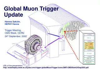
Global Muon Trigger Overview. 252 MIP bits 252 Quiet bits. 4 m RPC brl. 4 m DT. Inputs: 8 bit f , 6 bit h , 5 bit p T , 2 bits charge, 3 bit quality, 1 bit halo/eta fine-coarse. Best 4 m. 4 m CSC.

E N D
Global Muon Trigger Overview 252 MIP bits252 Quiet bits 4 m RPC brl 4 m DT Inputs:8 bit f, 6 bit h, 5 bit pT, 2 bits charge, 3 bit quality,1 bit halo/eta fine-coarse Best 4 m 4 m CSC Output:8 bit f, 6 bit h, 5 bit pT, 2 bits charge/synch, 3 bit quality,1 bit MIP, 1 bit Isolation 4 m RPC fwd
Input from RPC to GMT 8 bit f: 2.50 steps, bin 0 at interval 00 - 2.50OK 5 bit pT: Non-linear scale, must be indentical for RPC and GMT. pT =0 means no muon. OK 3 bit quality: New definition since 6-plane algorithm. OK ORCA to be updated. 6 bit h: Tower number for positive side. For negative side to be decided. ? Halo bit / fine eta bit: Not relevant for RPC‘s. 1 bit charge: 1 - negative, 0 - positive OK 1 bit charge validation: now computed by RPC OK 3 bits bunch counter: B2 B1 B0 OK 1 bit bunch crossing zero: BC0 OK 1 bit synchronization error: SE OK 1 bit clock: CLK OK
Bit Assignment and Hardware Assignment of input bits LVDS drivers and receivers Suggested: SN75LVDS387 16 bit LVDS driver SN75LVDT386 16 bit LVDS receiver Cables for parallel transfer Suggested: Madison cable: 34 pairs, 28 AWG, halogen free (order together with Wisconsin group)
Connectors SCSI-3 type connector Wire pairs: w1-w2 = pin 35-1, w3-w4 = pin 36-2etc.
Layout of USC55 Counting Room Racks Lower Floor Links ( ~5ns/m) + LVDS driver/receiver stages should not contribute more than 2-3 bx to latency. Need estimate of cable length.
GMT consists of 3 pipeline synchronizing boards (PSBs)… prototype available 1 GMT logic board… logic design completed FPGA design for GMT logic board in progress Milestones Dec 2002: logic design completed… completed Dec 2003: FPGA design done… progress as planned Jun 2004: GMT available Oct 2004: GMT tested GMT Hardware Status
URL’s and Documentation • This talk can be found at: • http://wwwhephy.oeaw.ac.at/p3w/cms/trigger/globalMuonTrigger/trans/ • GMT_RPC_warsaw.ppt • Detailed information about the Global Muon Trigger and the Global Trigger is • available on the HEPHY Vienna web sites: • http://wwwhephy.oeaw.ac.at/p3w/cms/trigger/globalMuonTrigger • http://wwwhephy.oeaw.ac.at/p3w/cms/trigger/globalTrigger • Draft interface document Regional Muon Trigger / GMT to be finalized: • http://wwwhephy.oeaw.ac.at/p3w/cms/trigger/globalMuonTrigger/notes/Reg_to_GMT_Note_0.91.pdf
Conclusions and Acknowledgements • Most of the issues of the RPC/GMT interface are settled. To be done: - Choice of cables and connectors - Coding of h - Update RPC and GMT codes in ORCA - Update documentation Special thanks to M. Kudla, H. Sakulin and A. Taurok.