Download
1 / 10
280 likes | 1.16k Views
Chapter 10 Atomic Emission Spectrometry (AES) 1 AES Based on Plasma. 1.1 Inductively coupled plasma (ICP) Three Argon flow Plasma gas (10-20 L/min) Nebulizer gas (~1L/min) Optional auxiliary gas (~0.5L/min) Radio-frequency (RF) power source up to 2kW Higher temp (~8000K)

E N D
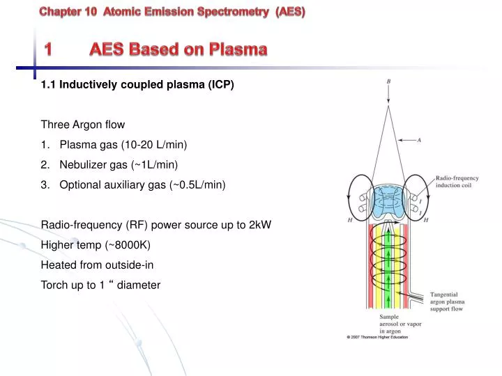
Chapter 10 Atomic Emission Spectrometry (AES) 1 AES Based on Plasma • 1.1 Inductively coupled plasma (ICP) • Three Argon flow • Plasma gas (10-20 L/min) • Nebulizer gas (~1L/min) • Optional auxiliary gas (~0.5L/min) • Radio-frequency (RF) power source up to 2kW • Higher temp (~8000K) • Heated from outside-in • Torch up to 1 “ diameter
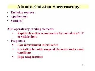
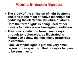
Plasma structure • Brilliant white core – Ar continuum radiation • Flame-like tail up to 2cm • Transparent region (15-20 mm above the core) – measurement made • Analyte atoms have 2 ms residence time and experience temperature from 5000-800K. Atomized in “inert” atmosphere. Little ionization. • Torch may be viewed radially or axially
Sample introduction 1. Nebulizer – convert solutions to fine spray or aerosol - Ultrasonic nebulizer uses ultrasound waves to boil solutions flowing across disc - Pneumatic nebulizer uses high pressure gas to entrain solution 2. Electrothermal vaporizer (ETV) Electric current rapidly heats crucible containing sample Sample carried to atomizer by Ar or He Only for introduction, not atomization 3. Other methods Direct insertion {powder placed inside flame, plasma, arc or spark atomizer} Laser ablation {uses laser to vaporize sample}
1.2 Direct current plasma DC current 10-15 A between C anode and cathode Plasma core at 10,000 K, viewing region at 5,000 K Simple, less Ar than ICP
1.3 Plasma source spectrophotometer 1.3.1 Sequential (scanning and slew-scanning) Slew-scan spectrometers – Rapidly scan (slewed) across blank regions Slowly scann across lines Computer control/preselected lines to scan
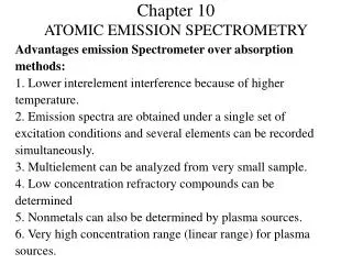
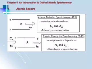
1.4 Plasma AES vs. Flame AAS AAS AES Similar atomization technique to AES Addition of radiation source High temperature for atomization Very high temperature for excitation (flame and electrothermal atomization) (plasma/arc/spark) Low cost instrumentation moderate-high cost Single element simultaneous multielement analysis Quantitative qualitative and quantitative Low sample throughput high sample throughput Atomization interference spectral interference (large # of lines) Detection limit 0.001-0.020 ppm 10ppb Greater precision complementary technique
2 AES Based on Arc and Spark Source * Limited to qualitative/semi-quantative analysis (arc flicker) Usually performed on solids Largely displaced by plasma-AES Sample pressed into electrode Electric current flowing between two C electrodes Cyanogen bands (CN) 350-420 nm occur with C electrode in air – He, Ar atmosphere Fig. 10-17 (p.270) Graphite electrode shapes
Arc/spark unstable – each line measure >20 s (needs multichannel detection) Photographic film - Cheap - Long integration times - Difficult to develop/analyze - Non-linearity of line “darkness” Multichannel PMT instrument • For rapid determinations (< 20 s) but not versatile • Routine analysis for solids – metals, alloys, ores, rocks, solids • Portable instruments
Spectrographs (record spectrum with a photographic plate at the focal plane)