Download
1 / 30
320 likes | 567 Views
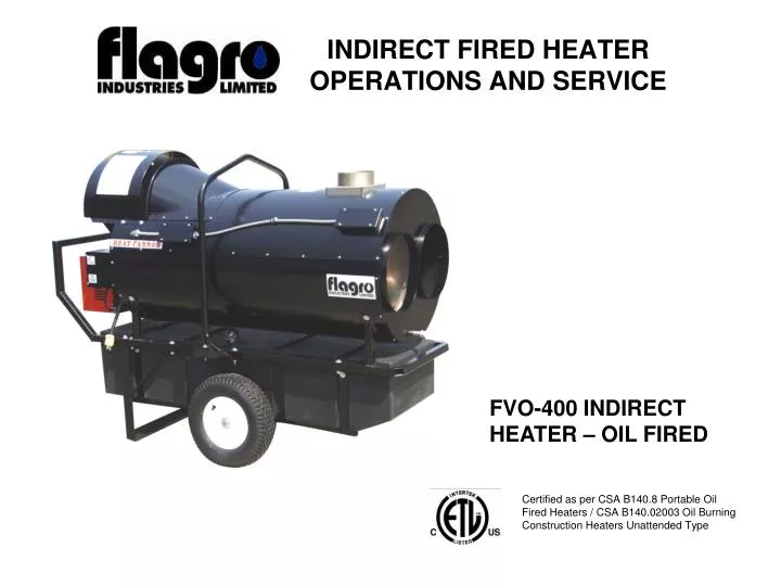
INDIRECT FIRED HEATER OPERATIONS AND SERVICE. FVO-400 INDIRECT HEATER – OIL FIRED. Certified as per CSA B140.8 Portable Oil Fired Heaters / CSA B140.02003 Oil Burning Construction Heaters Unattended Type. SPECIFICATIONS. Model - FVO-400 Input - 390,000 btuh

E N D
INDIRECT FIRED HEATER OPERATIONS AND SERVICE FVO-400 INDIRECT HEATER – OIL FIRED Certified as per CSA B140.8 Portable Oil Fired Heaters / CSA B140.02003 Oil Burning Construction Heaters Unattended Type
SPECIFICATIONS • Model - FVO-400 • Input - 390,000 btuh • Fuel - No.1, No. 2, diesel or kerosene • Fuel Pressure - 170 psi • Nozzle - 2.00 x 60 B or W (Delavan) • (Nozzles equipped with W7 S/S Filter inlet) • Ignition - Direct Spark • Air Circulation - 2500 cfm • Fuel Consumption - 2.75 Gal/hr • Approved - cETLus listed • Optional Thermostat Control
INSTALLATION CLEARANCE TO COMBUSTIBLES: TOP: 3ft FRONT: 10ft SIDES: 3ft REAR: 3ft FLUE PIPE: 3ft FUEL: This heater will operate with No.1, No.2, Diesel or Kerosene. Note:No.1 Fuel Oil or Kerosene must be used for temperatures less than –10º C (8º F). All units shipped in North America are equipped with a 2.00 x 60B or 2.00 x 60W nozzle. This nozzle allows for the increased density of oil/diesel fuel at colder temperatures. Pump pressure setting - 170psi
INSTALLATION ELECTRICAL: IT IS ESSENTIAL THAT THE HEATER BE SUPPLIED WITH ADEQUATE POWER TO OPERATE PROPERLY DEDICATED CIRCUIT – It is recommended that a dedicated circuit be provided to the heater with 115V supply and 15amp breaker HEAVY DUTY EXTENSION CORD – Due to the powder draw over distance, the following extension cords must be used: 12/3 AWG at 50 Feet 10/3 AWG at 100 Feet Using an undersized power supply cord will increase the amperage draw from the motor and potentially cause the heater to fail. This sort of failure can damage the ignition controls beyond repair and create an costly repair. MOTOR – The motor and burner on the FVO-400 draw a total of 10.5 amps. This allows some forgiveness in the field when jobsite power conditions are strained POWER INDICATOR – The heater is equipped with a power indicator light which helps detect various power supply issues such as: grounding issues, reverse polarity or missing connections.
POWER SUPPLY INDICATOR LIGHT (Not Applicable on HC Units) The power supply indicator light will help you detect any faulty power supplied to the heater including grounding issues, reverse polarity or missing connections WARNING LIGHT INDICATIONS Green Light - Meets Power Requirements Red Light - Reverse Polarity Flashing Red - Ground or Neutral Issue Light Red/Green - Excess Power Draw Flashing Light - Generator Power fluctuation (HZ) NOT TO EXCEED 62HZ
FLUE PIPE: The flue outlet connection on the heater is 6”diameter A - VENT TERMINATION MUST BE A MINIMUM OF 2FT HIGHER THAN ANY POINT WITHIN 10ft B - MAXIMUM HORIZONTAL RUN IS 30ft NOTE: 90deg ELBOW = 10ft HORIZONTAL VENT ALLOWANCE 45deg ELBOW = 5ft HORIZONTAL VENT ALLOWANCE D - EXTERIOR VERTICAL VENT TERMINATION MUST BE A MINIMUM OF 2ft
MAINTENANCE All fuel hoses should be visually inspected prior to firing up the heater. Check for wear or abrasion, cuts and or possible leaks at the fittings The fuel filter should be drained daily. Look for excessive dirt build up and/or water/ice. The fuel filter insert should be changed weekly. Fan limit switch should be replaced if the fan motor does not shut off once the heat exchanger has cooled down High Limit switches should be checked each season. These limit switches will ensure the burner shuts down if the temperature exceeds 150deg F at the rear of the unit and 250deg F at the outlet of the heater
Check the FAN BLADE to be sure the blade is moving freely to ensure the heater is drawing the correct combustion air. The HEAT EXCHANGER should be drained on a regular basis. There is a fuel drain located at the exterior of the heater. Check outlet on the HEAT EXCHANGERto ensure there are no blockages for the ventilation air. The HEAT EXCHANGER should be cleaned annually, using air or water, specifically if there is black soot at the outlet. This indicates that the combustion was incorrect. Once the HEAT EXCHANGER is clean, See Combustion Air Adjustments for the correct settings before firing the heater.
START UP INSTRUCTIONS: 1. Be sure the switch in is the “OFF” position. 2. Ensure electrical cord is grounded and heater is on a level surface. 3. Plug in supply cord to 115V 15amp outlet. 4. Move switch to “MANUAL” position for manual control. 5. Move switch to “THERMOSTAT” position for thermostatic control. Please Note: 1. If using Thermostat on unit, unit must be started in Thermostat position. 2. When changing between manual and thermostat operation, the heater must be left in the “OFF”position for 30 seconds to prevent the burner from locking out. 3. When using a generator for electrical supply, make sure the generator is properly grounded and generator is at a 60Hz frequency. 4. In the event that a Generator is being used and the generator runs out of fuel, make sure the heater switch is in the “OFF” position before restarting the generator, failure to do so may damage heater. TO SHUT DOWN: 1. Move switch to “OFF” position. NOTE: Fan will continue to operate after the burner shuts down. Once the unit cools down, the fan will stop.
IF HEATER FAILS TO START: • Press manual reset button at rear of burner. • Check fuel level. There must be 2-4 gallons of fuel in the tank for the heater to start properly. • Make sure there are no air locks in fuel lines or filter. • Ensure proper power supply and extension cord is being used. • Check for dirty fuel filter or blocked fuel supply line. • Check burner nozzle assembly. • NOTE: IF THE BURNER HAS BEEN RESET SEVERAL TIMES THERE MAY BE AN ACCUMULATION OF OIL IN THE CHAMBER! DO NOT CONTINUE TO TRY AND START THE HEATER! • DRAIN OIL FROM HEAT EXCHANGER USING DRAIN HOLE AT FRONT OF HEAT EXCHANGER FOR 15-20 MINUTES BEFORE ATTEMPTING TO RELIGHT. LET REMAINING EXCESS OIL BURN OFF BEFORE CHECKING COMBUSTION OF UNIT.
SAFE OPERATION PRECAUTIONS: • Do not fill fuel tank while heater is operation. • Do not attempt to start heater if excess oil remains in the heat exchanger. • Use switch to shut down the heater. Do not try to shut down the heater by unplugging the electrical cord. • Do not plug anything other than the thermostat into the “Thermostat” plug. • Do not use any fuel other that those listed on rating plate. • Follow electrical requirements shown on rating plate and/or Electrical requirements section of this manual. • Before removing any guards or performing any maintenance, be sure that the main power supply is disconnected.
COMBUSTION AIR ADJUSTMENTS: Proper combustion air adjustment must be achieved using a certified combustion analyzer and smoke tester to ensure complete combustion. The air adjustment should be made to achieve 10% CO2 and No. 1 or “trace” smoke. • Regulation of the combustion air flow is made by adjustment of the manual AIR ADJUSTMENT PLATE (1) after loosening the FIXING SCREWS (2 & 3). The initial setting of the air adjustment plate should be 4.5. • B) The proper number on the manual AIR ADJUSTMENT PLATE (1) should line up with the SETTING INDICATOR (4) on the fan housing cover. Once set, the air adjustment plate should be secured in place by tightening SCREWS 2 and 3. • C) The final position of the air adjustment plate will vary on each installation. Use instruments to establish the proper settings for maximum CO2 and a smoke reading of zero. • NOTE: Variations in flue gas, smoke, CO2 and temperature readings may be experienced when the burner cover is put in place. Therefore, the burner cover must be in place when making the final combustion instrument readings, to ensure proper test results.
COMBUSTION ANALYIZER TESTING: Ideal combustion readings: COppm – 0 to 20 ppm O2% - 5 to 7% CO2% - 9 to11% Excess Air – 35 to 45% Efficiency – 72-77% Stack Temp – 770 to 820 deg SERVICE TIP: When using the combustion analyzer, be sure to place the probe 18” above the flue to obtain the best reading. SERVICE TIP: If ideal combustion reading for COppm cannot be achieved by adjusting the AIR GATE and the excess air reading is high, it is possible that the BURNER TUBE GASKET is not sealed properly. This allows excess air to the HEAT EXCHANGER. Adjust burner gasket to ensure proper seal between the BURNER TUBE and HEAT EXCHANGER inlet. If COppm reading is high and excess air reading is normal it is possible that the TURBULATOR DISC is dirty. Clean the TURBULATOR DISC.
FEELER GAUGE: The temperature feeler gauge is required to be always touching the heater exchanger. The temperature feeler gauge controls the air flow over the fan switch, which eliminates any unnecessary fan cycling. In extreme cold conditions, cover the holes on the temperature feeler gauge using foil tape or replace with a solid state feeler gauge, part number FV-433B. Failure to do so may result in burning out fan switches- not covered under warranty.
REMOVAL OF DRAWER ASSEMBLY: A) To remove drawer assembly, loosen SCREW (3), then unplug CONTROL BOX (1) by carefully pulling it back and then up. B) Remove the AIR TUBE COVER PLATE (5) by loosening the two retaining SCREWS (4). C) Loosen SCREW (2), and then slide the complete drawer assembly out of the combustion head as shown.
NOZZLE PLACEMENT: • Remove the NOZZLE ADAPTER (2) from the DRAWER ASSEMBLY by loosening • the SCREW (1). • Insert the proper NOZZLE into the NOZZLE ADAPTER and tighten securely • (Do not over tighten). • Replace adapter, with nozzle installed, into drawer assembly and secure with • screw (1).
ELECTRODE SETTING: The most forgiving setting for the electrode placement is where the screw remains centered in the obround hole of the ceramic holder
TURBULATOR SETTING: A) Loosen NUT (1), then turn SCREW (2) until the INDEX MARKER (3) is aligned with the correct index number as per the Burner Set-up chart, on page 12. B) Retighten the RETAINING NUT (1) NOTE: Zero and five are scale indicators only. From left to right, the first line is 5 and the last line 0. Factory setting is 5 There is rarely a need to change this factory setting
HEAT EXCHANGER INSPECTION / TURBULATOR DISC: TURBULATOR DISC on the DRAWER ASSEMBLY should be inspected and cleaned if necessary. If there is soot on the TURBULATOR DISC, it is a good sign of improper combustion. To remove the TURBULATOR DISC for cleaning, loosen the screws at the rear of the assembly as shown. When the DRAWER ASSEMLBY is removed, it is an ideal time to inspect the interior of the HEAT EXCHANGER for carbon / soot build up due to improper combustion. Clean using compressed air or water if necessary.
RE-INSTALLATION OF DRAWER ASSEMBLY: • BE SURE: • Nozzle is tight. • Turbulator disc is clean and secure. • Electrode setting is correct and the ceramic • body is not cracked. • Re-insert drawer assembly in the burner tube. • Tighten the fuel line top pump motor. • Tighten the screw indicated to secure the drawer assembly. • Re-attach the air tube cover.
IGNITION MODULE / PHOTO CELL: The PHOTO CELL is attached to the underside of the IGNITION MODULE. Ensure that the eye of the PHOTO CELL is clean and secure. Inspect the IGNTION MODULE for burn marks at the front of the module and for cracks in the housing. Both of these defects can be caused by excessive heat. Inspect the CONTROL SUB BASE to ensure all wiring and terminals are in the correct position. Refer to troubleshooting illustration in the OPERATIONS MANUAL. Note: Bent terminals will cause ignition failure. When re-installing the IGNITION MODULE be sure to slightly tip the module forward. Lining up the ignitor probes with the plastic inlets of the module. The PHOTO CELL must also be lined up with the hole in the air tube cover. Level the module on the sub base and push gently until it is secure. Tighten the side screw to complete the installation.
OIL LINE CONNECTIONS: (6) Indicates the fuel pump supply line. (9) Indicates the fuel pump return line. (4) Indicates the PUMP BYPASS PLUG. This plug is installed at the factory. Note, when replacing a FUEL PUMP, this bypass plug must be installed in the return side of the pump before the fuel return line attached. Failure to install this bypass will prevent the burner firing. Also note, there is a white plastic DRIVE KEY (FVO-3000443) on the shaft of the pump motor. Be sure this key is secure before installing the new PUMP MOTOR.
PUMP PRESSURE SETTING: Pump pressure is factory set at 170psig. A pressure gauge should be attached as shown to the PRESSURE PORT (8) (previous page) to confirm the pump pressure is correct. Note the adaptor for this port is British Parallel Thread design. Direct connection of NPT threads to the pump will damage the pump body. Riello manometers and vacuum gauges do not require any adaptors, and can be safely connected to the pump ports. An NPT (metric) adapter must be used when connecting other gauge models.
TROUBLESHOOTING PROBLEM: BURNER WILL NOT GO INTO PRE-PURGE Confirm power supply – is power indicator light green? See POWER INDICATOR LIGHT instructions to help determine power issues. Confirm power to both rear and outlet HIGH LIMIT switches using a volt meter. Ensure all spade connectors are secure and crimped properly. Replace limit switch if necessary – if power is not found on both sides of the switch. Check connections on control sub base. Make sure none of the tabs on the sub base are bent and losing connection with the IGNITION MODULE.
PROBLEM: FAN MOTOR DOES NOT ENGAGE Confirm power on both sides of FAN LIMIT. Replace FAN LIMIT if necessary. Confirm power on both sides of RELAY. Replace RELAY if necessary. Check connections on motor overload. If motor overload connections are corroded it will prevent the motor from operating properly. Check both the START and RUN CAPACITORS. Use volt meter to confirm OHM reading from CAPACITOR terminals to ground. If OHM reading is close to zero, the CAPACITOR should be replaced. Note: Heater must be plugged in to power to perform this check.
PROBLEM: BURNER STAYS IN PRE-PURGE – DOES NOT LIGHT Inspect PHOTO CELL. Ensure the eye of the PHOTO CELL is clean. Ensure the PHOTO CELL is secure on IGNITION MODULE. Note: Always replace the AIR COVER on the burner assembly before starting the burner. If this cover is not installed, natural light can trick the PHOTO CELL into thinking there is flame. SERVICE TIP: Remove PHOTO CELL and re-install the IGNITION BOARD. Try for ignition, if burner now fires and locks out, then PHOTO CELL should be replaced.
PROBLEM: BURNER IGNITES AND LOCKS OUT IMIMEDIATELY: Check COMBUSTION AIR SETTING. Be sure the AIR GATE is set to the correct setting. Typically this setting is 4.5. See COMBUSTION AIR ADJUSTMENTS page. Check fuel supply. Make sure the clear fuel lines are not blocked and there are no signs of air in the lines. Make sure all connections are tight. Inspect the FUEL FILTER. This FUEL FILTER should be changed weekly. Be sure there is no debris or ice inside the FILTER. Change NOZZLE. It is possible the NOZZLE is not allowing fuel to pass properly. Replace if necessary. The NOZZLE should be replaced annually.
Confirm pump pressure during PRE-PURGE. If the pressure during pre-purge is not between 50-100psig the pump motor may need to be replaced. Check VACCUM pressure on PUMP. Attach vacuum gauge to the vacuum port shown here. While the burner is in pre-purge, the reading should be no more than 11” W.C. If the reading is higher, there is most likely a blockage in the fuel lines.
PROBLEM: BURNER TRIES FOR IGNITION & LOCKS OUT: Check FUEL LINES. Make sure there are no air bubbles in the clear FUEL LINES. SERVICE TIP: If the pump motor has been replaced, make sure the bypass plug has been properly installed in the return side of the pump. Check IGNITION MODULE. Make sure the module is secure to SUB BASE and the terminals are not bent. Make sure the ignitor probes are installed properly into the IGNITION MODULE. Replace IGNITION MODULE if necessary. Check IGNITOR ASSEMBLY. Make sure the ceramic assembly is not cracked or damaged. Make sure the gapping between the probes and face of the NOZZLE are correct.
IDEAL SETTINGS FOR NORTH AMERICA - FVO-400 Due to the cold temperatures, nature of the fuel and variation in altitudes in North America, we recommend the following settings for the FVO-400 Indirect Fired Oil Heater: Nozzle - 2.00 x 60B (alternate 2.00 x 60W) (Nozzles equipped with W7 S/S Filter Inlet) Pump pressure - 170 psi Air gate setting - 4.5 Power requirements - 15 amp dedicated circuit for each heater Note: The total running amp draw of the heater is approx. 10.5 amps including the blower motor and burner.