Download
1 / 16
160 likes | 317 Views
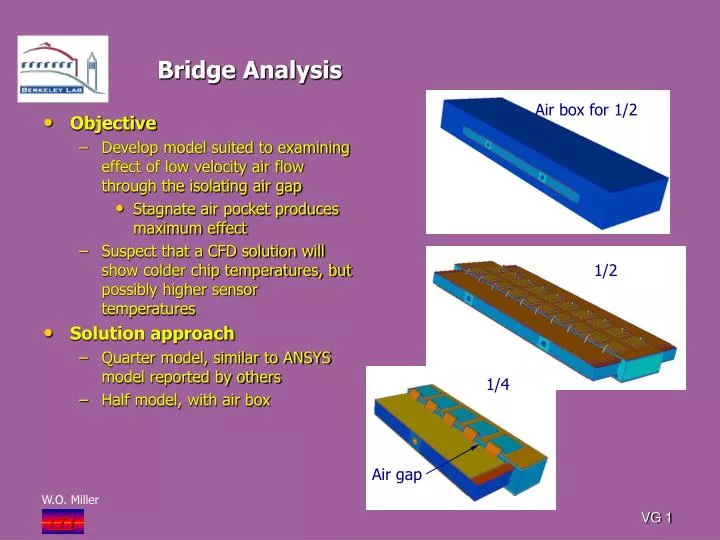
Bridge Analysis. Air box for 1/2. Objective Develop model suited to examining effect of low velocity air flow through the isolating air gap Stagnate air pocket produces maximum effect Suspect that a CFD solution will show colder chip temperatures, but possibly higher sensor temperatures

E N D
Bridge Analysis Air box for 1/2 • Objective • Develop model suited to examining effect of low velocity air flow through the isolating air gap • Stagnate air pocket produces maximum effect • Suspect that a CFD solution will show colder chip temperatures, but possibly higher sensor temperatures • Solution approach • Quarter model, similar to ANSYS model reported by others • Half model, with air box 1/2 1/4 Air gap VG 1
Bridge Model-Foam Support Contacts Facing • Two FEA Models • Quarter model • Air gap (1mm) confined to region directly beneath the bridge, presumably simulated arrangement used by others with ANSYS • Wire bonds simulated with wide thin sheet , 2mils thick • Initial mesh problem solved by breaking thin sheet into two solids • Heat load, 0.25W/chip, total 10chips • Cooling tube wall reference temperature, -28ºC • Half Model • Air space encloses bridge, allowing three-dimensional affects • Space beneath bridge remains 1mm • Wire bonds, simulated with narrow band, improved aspect ratio to fix mesh issues observed in the quarter model • Treated as one solid • Heat load, 0.25W/chip, 40chips • Cooling tube reference temperature, -28ºC VG 2
Model: Adhesives and Cable Definition Cable definition combines two layers of adhesives with cable VG 4
Bridge Model-1/4 Size • Solution • With air and with wire bonds • Peak chip, -5.84ºC • Range in sensor temperature • -20.0ºC to -24.4ºC • Warmest on point sensor is directly beneath bridge where bridge foam contacts the facing Sensor -20ºC VG 5
Quarter Model • End view • Illustrates temperature gradient through 1mm thick air gap • Temperature gradient in gap at center plane is 16.75ºC • Separation between solids is space represented by shell elements • Account for thermal resistances of adhesives and cable Air gap Shell element region, typical VG 6
Half Model: Without Air Box • Half-Model Bridge Support: • Wire bonds are present. • Peak chip is -1.85ºC • Quarter Solution • Same conditions, peak chip temperature is -2.12ºC • Good agreement • In spite of different mesh size and meshing issues VG 7
Half Model: With Air Box • Thermal Solution • Air box surrounds the half model • Result is that the bridge runs a bit cooler • Peak chip is -6.85ºC versus -5.84ºC from the quarter model • Next step • Investigate low velocity thru air box VG 8
Half Model: With Air Box • Temperature profile with air box removed • Profile with bridge removed VG 9
Multiple Sensors –Convective Cooling • Convection • -25C air flows over and under the bridge • Initial velocity entering air box=.01m/s Peak chip -6.19C VG 10
Multiple Sensors –Convective Cooling • Air box VG 11
Multiple Sensors –Convective Cooling • Isotherm taken thru box Peak chip=-6.19ºC Next step is to solve with -15C VG 12
Model Results VG 13
Multiple Sensors –Convective Cooling • Solution with -15ºC • Use second and third chip to avoid entrance effects and exit effects • Sensor temperature ranges from -18.7ºC to -24.7ºC Section cut of isotherms VG 14
Multiple Sensors –Convective Cooling • Section cut of velocity flow field • Air flows over chip, essentially no flow under bridge • 15ºC air does not have appreciable effect on sensor, more effect on peak chip temperature Velocity flow over bridge ~.01m/s Essentially zero VG 15
Multiple Sensors –Convective Cooling • Section cuts for temperature and velocity fields VG 16