Download
1 / 14
140 likes | 144 Views
Summary of thermal conduction gas tests for ANITA. Goal: To measure the heat transport of different gases in a force-convection environment. John Clem, Anita Collab. Mtg., Mar 10-13, 2004. Physical Properties of gases used in this Survey. John Clem, Anita Collab. Mtg., Mar 10-13, 2004.

E N D
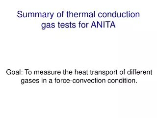
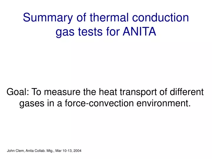
Summary of thermal conduction gas tests for ANITA Goal: To measure the heat transport of different gases in a force-convection environment. John Clem, Anita Collab. Mtg., Mar 10-13, 2004
Physical Properties of gases used in this Survey John Clem, Anita Collab. Mtg., Mar 10-13, 2004
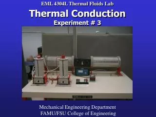
Bartol Setup The measurements were made using a 14” diameter by 26” long drum with 2 standard indoor / outdoor thermometers to measure temps inside. The drum has two holes for gas exchange and a third for wire feed through. John Clem, Anita Collab. Mtg., Mar 10-13, 2004
Setup at Bartol A 2.6ohm resistor was placed on a large Al heat sink plate as shown above. The resistor was placed in one of the two large gap between the fins while the temp sensor placed on the other large gap. Another sensor was place on inside surface. The system was mounted on ¼” piece of lucite. John Clem, Anita Collab. Mtg., Mar 10-13, 2004
Time profile of the temperature for Nitrogen and Neon/Helium Heatsink resistor dissipate 120Watts and the fans dissipate 6 Watts total (~5% contribution). The dashed lines represent the results with Nitrogen while solid is the Neon/Helium mixture The temperature difference of the heat sink to the ambient (red) and the heat sink to the cylinder surface (black). John Clem, Anita Collab. Mtg., Mar 10-13, 2004
Time profile of the temperature differences between the Heat Sink and the cylinder surface which are the dashes lines. The solid lines are the temperature difference between the Heat sink and ambient. The gases tested are Nitrogen, Neon, Sulfur Hex and helium John Clem, Anita Collab. Mtg., Mar 10-13, 2004
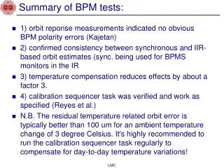
Relationship between fan electrical current and gas density. Additional input power from fans is considered in the thermal model. It is unknown if the fan displacement/velocity is effected by density. John Clem, Anita Collab. Mtg., Mar 10-13, 2004
Pr = Cpυ / ρ λ Prandtl number dT= Heat Sink to Room Re = V L / υ Reynolds number υ = viscosity λ = conductivity Cp = Specific Heat Capacity ρ = density V = gas velocity L = characteristic length dT= Heat Sink to inside surface Simple horizontal flat plate model for force convection cooling taken from "Technical Guide to Thermal Processes" by J. Gosse 1986.. This model provides a nice ordering parameter, however our heat sink has a more complicated geometry. The fan current is used solely to correct the internal input power. John Clem, Anita Collab. Mtg., Mar 10-13, 2004
Pr = Cpυ / ρ λ Re = V L / υ υ = viscosity λ = conductivity Cp = Specific Heat Capacity ρ = density V = gas velocity L = characteristic length An unknown thermal system can be modeled by consider the power indices on the Prandtl and Reynolds number as free parameters. Our approached is to adjust the two indices such that the calculated temperature differences (x-axis) are directly proportional to the observed values (y-axis). The x-axis scaling is arbitrary. This was perform by choosing indices which yields the minimum chi-square to a least squares linear fit to the dT data between the heat sink and the cylinder wall. This quantity serves as far better ordering parameter Obviously, the heat sink to room temperature difference has an additional transport region to consider (room air to sensor) which is reflected by the offset.
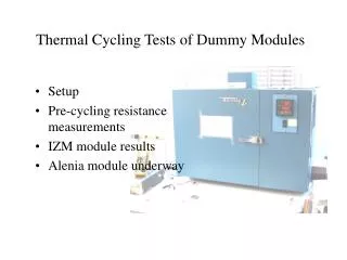
ANITA Compact PCI crate gas Temperature Test at UH (Jason Link and Marc Rosen) • Testing was done using a compact PCI crate same as used in Anita-Lite • The crate was set on a cardboard box to thermally isolate it and enclosed inside a 55 galloon steel drum • The temperature inside the laboratory was monitored as well as three temperatures inside the can – the temperature on the inside wall of the steel drum, the temperature of the air in the steel drum and the temperature of a built in sensor on the Acqiris module. Gas inflow and outflow Power, network and sensor cables Compact PCI crate Cardboard Box to thermally isolate PCI crate USB Hard Drive Can Temperature Sensor (T1) – Not Visible Air Temperature Sensor (T2)
Argon Test • After ~80 minutes of turn-on Acqiris temperature reached 49 C so the system was shutdown to avoid damage. • Argon is probably ~not~ a good gas to use during flight. • Nitrogen Gas Test • After about 2 hours the system seemed to stabilize • Acqiris Module temperature was 44 C which was 10 degrees warmer than the ambient temperature of the Nitrogen inside the can. John Clem, Anita Collab. Mtg., Mar 10-13, 2004
Neon Gas Test • Stabilization after about 3 hours • A network problem caused a loss of Acqiris temperature data for about 30 minutes. During this time the computer was unplugged and powered up 3 times. • Acqiris temperature stabilized at about 45-46 C • Cooling performance is about the same as Nitrogen, perhaps slightly better. • Sulfur Hexafluoride Gas Test • Stabilization after about 2 hours. • Acqiris temperature stabilized at 41 C. • Cooling performance is better than Nitrogen, the Acqiris boards seems to have stabilized at a temperature 3 degrees cooler than for Nitrogen. John Clem, Anita Collab. Mtg., Mar 10-13, 2004
The concept of gas as an insulator is currently being used in the Home Window Industry. As we know Argon makes a great heat insulator and not the right choice for our needs. It seems SF6 is best choice within this survey for our flight gas John Clem, Anita Collab. Mtg., Mar 10-13, 2004
The Results of the Bartol and UH tests are consistent with each other. Our model seems to be able to predict results adequately for choosing an new candidate for testing. In a system where force-convection is the dominate heat flow component, the heat conductivity, heat capacity, density and viscosity of the gas must all be considered in the modeling. Of our survey of gases SF6 seems to be the best gas at transporting heat in a force-convection environment.. Publishable in NIM ??? If so, probably should repeat measurements under better control for gas purity and fan displacement John Clem, Anita Collab. Mtg., Mar 10-13, 2004