Download
1 / 16
160 likes | 286 Views
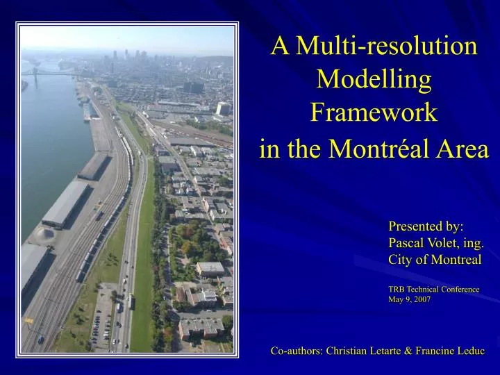
A Multi-resolution Modelling Framework in the Montréal Area. Presented by: Pascal Volet, ing. City of Montreal TRB Technical Conference May 9, 2007. Co-authors: Christian Letarte & Francine Leduc. 1. Introduction

E N D
A Multi-resolution Modelling Framework in the Montréal Area Presented by:Pascal Volet, ing.City of MontrealTRB Technical ConferenceMay 9, 2007 Co-authors: Christian Letarte & Francine Leduc 1
Introduction • In order to fulfill its responsibilities in terms of urban development and accessibility, the City of Montreal faced the fact that it had to be better equipped in terms of modelling and forecasting. L’Acadie Interchange Parc / Pins intersections Notre-Dame/Sherbrooke Roundabout
Modelling in the Montreal Area Its Strengths : - 25 years of experience based on rich OD surveys (5% household sample every 5 years) - Integrated regional modelling of transit and auto - Implemented at the modelling group (SMST) of MTQ(Ministry of Transportation for the province of Québec) - Dependable traffic volumes on the primary road network - Can generate sub-area demand matrices - Only tool for traffic forecasts (external inputs needed) - Recently adapted to tour-based modelling (mode switching) The EMME/ 2 based regional model
Modelling in the Montreal Area The EMME/ 2 based regional model Its limitations : - Simulation of congestion and gridlock (static model) - Implicit land-use (involves external data input for major changes) - Aggregate intersection control analysis (Volume/Delay curves) - Notre-Dame Project : Regional calibration not adapted to the smaller project area Montréal regional data R² = 0.89 Notre-Dame Project area data R² = 0.56 R² : Statistical measure of how well a regression line approximates real data points The objective for a transportation simulation model is a value of 0.90 and above
Modelling in the Montreal Area The Dynameq modelling tool • Requirements for software implementation • Creation of a dedicated modelling team within the Notre-Dame modernization project(model set-up and data collection) • Collaboration with the MTQ in exporting the base data from the regional EMME/2 model (EMME/2 operated at the City with MTQ oversight) • Continual updating of changes within the study area perimeter (signal timing and phasing, stop controls, signing and striping, etc.) The original analysis network, extracted from the EMME/2 regional model The choice of unreleased software* in 2004 was a risky decision, but the results have been conclusive and successful. * Dynameq 1.0 officially released in 2005, now at version 1.2
The traffic and travel modelling componentsat the City of Montreal Chronic road congestion problems call for specialized tools in order to pinpoint the impact of transportation network improvements Static Assignment – Regional ModelLarge ScaleEMME Software New DomainSoftware in development Dynamic Assignment – Urban ModelMedium ScaleDYNAMEQ Software Micro-simulation – Arterial ModelSmall ScaleSimTraffic or VISSIM Software For solving existing traffic problems or forecasting future transportation conditions, simulation models are at the centre of all analyses
Dynameq Output Results When comparing similar modelling areas, dynamic assignment based Dynameq is more precise than the static based EMME/2 regional model EMME/2 DYNAMEQ Notre-Dame project areaR² = 0,88 Notre-Dame project areaR² = 0,56
Dynameq Output Results Travel times vary from 3 to 25 minutes observed per segment AM peak hour – travel time in seconds PM peak hour – travel time in seconds Travel time data collection – 21 runs yielding 39 segments
Dynameq Output Results Traffic situation on the network during the PM peak (5:15) Congestion – Sherbrooke St. approach to Papineau (RT) Congestion – Ontario St. approach to Papineau (RT) Congestion – Notre-Dameapproach to Frontenac (LT)
Dynamic assignment advantages Comparing various design options allows for optimization of the ultimate solution The differences are in the geometric configuration to the Ville-Marie tunnel westbound approach. Option X Option Y For Option Y congestion begins after de Lorimier Street For Option X congestion begins before de Lorimier Street
Dynamic assignment advantages Several different design projects can be evaluated simultaneously Dickson Street closure L’Assomption Blvd. extension Viau and St-Clément functionning as two-way streets Pie-IX / Notre-Dame grade separation Souligny Ave. Extension and new neighbourhood connections
Other Dynameq Applications Long term construction mitigation measures can be tested • Mitigation construction example for the Notre-Dame project: • One lane per direction onNotre-Dame (instead of 2), between A-D-Roy and Ste-Catherine • One lane per direction on Ste-Catherine (instead of 2), between A-D-Roy and Notre-Dame Difference beween the mitigated scenario and the present situation Increase on Sherbrooke Increase on Frontenac Increase on Hochelaga Increase on Ste-Catherine Decrease on Notre-Dame
Limits of the dynamic assignment tool • Conventional micro-simulation tools needed in order to perform the following tasks • Detailed multiple lane changing behaviour, lane sharing • Pedestrian and cyclist interaction • Individual vehicle queueing visualization • Signal timing and phasing optimization (Synchro/SimTraffic)
The current and future expansion planned for the Dynameq-based modelling area Working hand-in-hand with MTQ (SMST) to calibrate the freeway network and its transitions to the City’s arterial streets Total Area = 350 km2 150 km2 50 km2 50 km2 100 km2
Conclusion The future of modelling at the City of Montreal Berri - UQAM Aut. Bonaventure CHUM