Download
1 / 28
280 likes | 396 Views
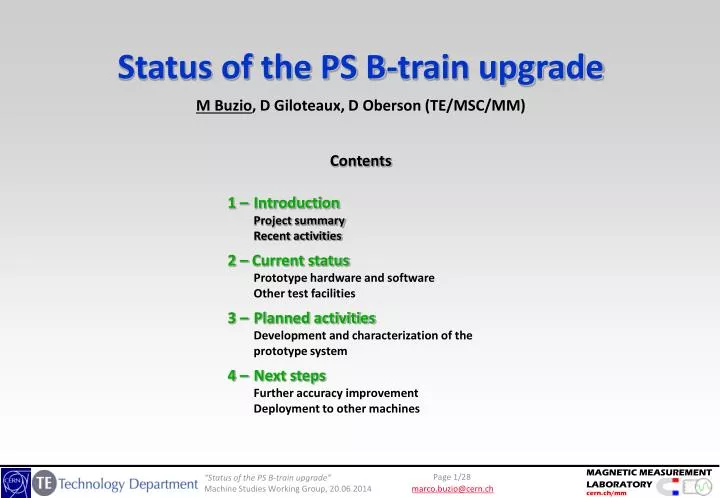
Status of the PS B-train upgrade M Buzio , D Giloteaux, D Oberson (TE/MSC/MM). Contents 1 – Introduction Project summary Recent activities 2 – Current status Prototype hardware and software Other test facilities

E N D
Status of the PS B-train upgrade M Buzio, D Giloteaux, D Oberson (TE/MSC/MM) Contents 1 – IntroductionProject summary Recent activities 2 – Current statusPrototype hardware and softwareOther test facilities 3 – Planned activitiesDevelopment and characterization of the prototype system 4 – Next stepsFurther accuracy improvementDeployment to other machines
Acknowledgment • Thanks to S. Gilardoni (BE/ABP), R. Steerenberg and the whole PS operation team (BE/OP) for motivating the B-train upgrade project and supporting the necessary tests • Thanks to F. Caspers (BE/RF) for hisessentialsupporttowards FMR development • Thanks to H. Damerau (BE/RF), J. L. Gomez Costa, Q. King (TE/EPC), P. Odier, L. Soby (BE/BI), J. Serrano (BE/CO) for their collaboration towards the definition of the new serial distribution link • Thanks to A. Beaumont, D. Bodart, G. Golluccio, O. Dunkel, L. Gaborit, P. Galbraith, R. BeltronMercadillo (TE/MSC) for their technical and scientific contribution to the project
History recap 2000 Current Mark III electronics installed and maintained by P. Dreesen and his team (TE/EPC). This system uses pick-up coils in both F/D halves of U101, but peaking strip markers only in F 2006 TE/MSC/MM takes on responsibility for real-time magnetic measurement systems 2011 Mark IV B-train upgrade project green-lighted by IEFC Hardware R&D 2008 NMR marker @ 60 mT with passive ferrite gradient compensation 2010 Omni-Yig polycrystalline FMR Off-line diagnostic “spy” system 5x pick-up coil array for multipoles Beam instability investigations2010 14 mm MRP oscillation after I8 on zero cycles linked to undetected F/D imbalance2011 Bdot noise linked to the initial lack of filters to GND for POPS2011 Instability at injection on the 2nd CNGS cycle only after low-energy cycles2012 Tune decay @ 26 GeV linked to 50 msquadrupole eddy-current field decay 2014 Identification of the source of A3 in the bare machine (ongoing)
Functional specifications • Why to build an upgraded system for the PS ? Improvements are needed along three axes: • Reliability new markers as a long-term alternative for difficult-to-replace peaking strips reduction of down time due to timing conflicts (synchronization between peaking strip window and current cycles; internal integrator recalibration) more robust signal transmission remote diagnostics • Operational flexibility • sensors in both F/D halves to recover full information mitigate B-train errors due to the imbalance induced by specific operation sequences that today are best avoided (e.g. F8 degaussing cycles, certain combinations of cycles) allow higher flat-bottoms and thus shorter cycles (NB: the current very low 5 mT value is imposed by the peaking strips !) • remote switching between OP and SPARE chains • Precision and accuracy5 µT resolution (currently limited by the repeaters) more accurate integration, drift correction more flexibility in the calibration and in adapting to new operation modes
Mark IV B-train Main design choices: Modern electronics (integrator, marker trigger generator) based upon CERN-supported solutions (Industrial PICMG1.3 PC + SPEC PCIe carried card + FMC mezzanine) Software compatible with accelerator control systems (CERN Scientific Linux + FESA) Field markers based on commercially available components (FMR resonator / NMR probes) Optical-fibre serial transmission of numerical measurement results(OpenHardware White Rabbit) New timing-independent, streaming integration and drift/gain correction algorithms
Streaming integration • New concept: continuous digital distribution of B(t)on a fast serial line to replace old pulse train • Output stream continuously updated with current B(t) values no need for complex triggering and reset logic; no B0 initialization burst • Adaptive auto-calibration of gain and offset using field markers on flat-top and flat-bottom fully transparent correction of measurement error • fast and robust transmission,no more timing conflictsbut: drift correction must be applied continuously on-the-fly ADC offset ( integrator drift) updated every time the same marker level is reached Integrator gain error updated every time a different marker level is reached N different marker levels up to 4 N corrections per cycle Corrections smeared over a certain t to avoid sudden jumps
Mark IV B-train Stagedroll-out proposal: Mark IV.0 (prototype) – 2014/2015 Mark III in // to prototype electronics/firmware + 2× FMR markers Mark IV.1 – 2015: Mark III in // to pre-series electronics + new sensors (high field markers, advanced coil arrays) Mark IV.2 – around LS2 ? Drop Mark III, production electronics + integral coils
Mark IV.0 – Prototype electronics in U101 2× AnaPico20 GHz signal generators for F,D FMR (local frequency setting only) B-train chassisincluding: 8-page multi-function display,analog and digital I/O, RF amplifier, power supplies SPEC FMC 2-ch. integrator card- “classic”integration reset at c0 + weighted sum of F/D integrals- basic offset correction- software-configured ADC/preampli calibration with internal voltage reference, automatically due during zero cycles (NB yearly offline calibration still necessary) OP system SPEC FMC 2-ch. marker card- trigger generation with high-Q FMR- trigger generation with NMR all functionalityquoted tested Commercial White Rabbit switch Switching chassis- simulated/measured B-train (based on POPS being on/off)- OP/SPARE B-train (HW signal from CCC) SPARE system Front End industrial PC New high quality PFW/I8 DCCT outCourtesy O. Michels
White Rabbit distribution • All cabling + spares in place • Broadcast mode with two switches tested @ 250 kHz (50 design target, 300 theoretical max.)first test results: 5.6 µs latencyseen by POPS receiver • P.C. broadcast internally measured current 1 kHz, 1% on-the-fly B(I) simulation for:- timing-independent marker trigger enable- telegram-independent cycle recognition- internal diagnostics and alarms- simulated B-train in case of measured B-train failure (?) Large headroom for expansion Implementednow planned:same as POPS In operation lab testsOK Tx testsOK
Mark IV.0 (currently installed) – Sensor configuration B-UP B-DOWN • Aim: • characterise hardware components, firmware algorithms and WR communications • obtain same functionality as Mark III (integrator reset @ c0) with maintainable electronics/markers • verify the advantages of a second 60 mT marker in F half Mark III B-train prototypeharmonicarray FMR LO peaking strips fluxloops fluxloops peaking strips FMR LO Mark IV B-train 001011011011100
Recap: NMR vs. FMR markers Sensor output during a field ramp in “marker mode” (fixed frequency excitation) 10 T 100 T NMR FMR
Metrological characterization of FMR field marker • Calibration of a factory-optimized Noryl-case resonator in a reference dipole vs. NMR: • DC reproducibility: 0.04 G over the range 550 to 1200 G • Ramp reproducibility: 0.1 G @ 600 G, 2.4 T/s • Temperature dependence: 0.04 G/C (2C in U101 close to tolerance !) • Roll angle dependence: 0.04 G/mrad @ 600 G; non-linearity vs. B disappears at certain angles very difficult to use in teslameter mode; strict mechanical tolerance in marker mode • Resonance spread due to B: still very good Q1000 at B/B=4.6 m-1 (as in U101) nominal horizontal mounting non. linearity error vs. B, roll angle ramp-rate dependence reproducibility
Spy system • Based on National Instruments hardware: PXIe chassis, RT controller, 2 6366 DAQ cards (82 MHz parallel 16-bit channels + 3210MHz digital I/O channels) • Acquisition of all sensors and B-train signals • Introduced in 2010 to track the magnetic state in F/D halves • Used to check the consistencyof sensor and B-train signals, timing and currents • Testbed for the design of new sensors and acquisition algorithms • System ready to resume (after disk clean-up) • New high-quality F8 + PFW current readout from DCCT (courtesy of O. Michels) still to be cabled and tested
B-train test bench • Test bench equipped with a dipole magnet ramping up to 10 T/s, FGC2 power supply • New RP zone in I8 being set-up, expected in operation this summer • Aim: - calibration of FMR markers vs. a combination of NMR marker + flux loop (mini B-train)- stand-alone test bed for B-train electronics/algorithms- stand-alone test bed for FGC3 control algorithms and NMR readout software (with TE/EPC) • Upcoming test campaigns:- calibration of single-crystal FMR markers (one installed, 4 additional units in stock)- characterization of upcoming high-field and polycrystalline FMR markers
What’s next • Finalization and debugging of the firmware/VHDL/Linux device drivers • Communication with CCC via FESA: develop the classes discussed with OP team • Integrator: VHDL timing registers to check and control + DMA transfer data • Local FMR frequency control • Dynamic (smoothed) adjustment of the integrator offset/gain upon reception of marker triggers • Etc. etc. … • Component-level tests • Drift error statistics vs. machine cycles, ambient conditions definition of marker levels, frequency of correction etc .. • White Rabbit communication to/from all users • Offline system-level tests • Mark IV = Mark III using same sensors (coils + 1x peaking strip in F) • Mark IV ≥Mark III using augmented sensors (coils + 2x peaking strips in F/D) • Mark IV ≥ Mark III using new sensors (coils + 2x FMR in F/D)compare repeatability of FMR vs. P.S./beam as a function of cycling, ramp rate, temperature … • Online system-level tests • run the machine with the Mark IV system
Recap: magnetic length • In the “hard edge” model, the magnetic length is used to express integrated strength as a function of central field • LmLiron core (the = holds for permanent magnet arrays) • as used by many codes (e.g. MAD), the choice of Lm is largely arbitrary as long as the correct integral results • typically, in short magnets saturation affects the ends more than the center Lm(I) drops at high field • B0 • saturation
B-train calibration • Mark III: calibration depends upon the position of coils and peaking strips and is built-in in the coil surface areas and peaking strip excitation currents – the results is rigidly fixed (NB: the installed flux loop take practically a point-like measurement) • Mark IV: flexible system takes into account explicitly the relationship between local and integral field values vs. current (also cycling, ramp rate …) • Calibration coefficients λm, λc for all markers and coils can be computed/measured in U17/obtained from comparison vs. beam energy coil position marker position average magnetic lengthof one unit “implicit” user factor average field measured by the B-train
High-field marker • Recent tests for MedAustron B-train evidence clearly that the magnetic length is much more history-dependent at low than high field increased precision by marking at the flat-top for drift correction • To be evaluated: trade-off with larger integrator drift during ramp-up • To be evaluated: trade-off with smaller dynamic range for gain correction (mid-level marker is best ?) Courtesy G. Golluccio
High-field FMR • High field marker is beneficial for accurate drift correction, essential for gain correction • Current units are limited about 9 GHz @ 28 GHz/T 0.3 T • Range of peak field of interest: 1.26 T (PS) to 2.02 T (SPS) 34 to 57 GHz !! • Single-crystal units in the 20-30 GHz range being manufactured by OmniYig • … rather expensive test equipment to be procured … Programmable Frequency Synthesizer + RF amplifiers for operation in marker (fixed-frequency) mode Network Analyzer for characterization and calibration
Field harmonics in bare magnet @ injection • First-time high-precision harmonic measurements vs. I(t)(B1-B15, A1-A15, magnetic axis, field direction) • Tests to be carried out on U17 in bldg. 150 with a 34 × 750 mm quadrupole-compensated rotating coil • Locally available power supply has acceptable stability up to about 600 A (1500 G) • Caveat: reconstructing a meaningful integral inside a curved magnet requires very accurate position measurements and mathematics still under development … Stepwise measurements centred in all blocks in sequence
Mark IV.1 – Sensor configuration B-UP B-DOWN • Aim: • enable faster/magnetically more stable operation with 60 mT flat-bottom cycles (Mark IV only) • improve accuracy:- streaming integration i.e. continuous drift correction for true machine timing independence- high field FMR markers for relative gain calibration- NMR markers for absolute gain calibration- new rectangular harmonic PCB coil array for well-conditioned field harmonic integration- more sensors to capture eddy current effects/saturation in the end regions ( additional, independent integration channels) Mark III B-train rectangularharmonicarray rectangularharmonicarray FMR HI FMR HI fluxloops fluxloops peaking strips peaking strips NMR NMR FMR LO FMR LO Mark IV B-train 001011011011100
Mark IV.2 – Sensor configuration • Ideal final configuration: • drop all legacy sensors and electronics • free pole gap to fit in integral coils + multiple markers in the linear/saturated regions for best possible integral accuracy FMR HI FMR HI NMR NMR FMR HI FMR HI 10 × rectangularharmonic arrays FMR LO FMR LO FMR LO FMR LO Mark IV B-train 001011011011100
CERN-wide deployment plan • Approved/budgeted: PS, PSB, ELENA • In all cases: existing systems to be tested in parallel with new one • All necessary resources (esp. manpower) not allocated yet
Conclusions • Getting closer to initial goal i.e. future-proof alternative to existing B-train • Lots of potential for improvingdramaticallyaccuracy and extending the benefits to other machine • Work more difficultthananticipated, lack of manpower • To be circulated for approval/published: - detailed list of signals to be exchanged with CCC via FESA (or Oasys)- detailed test time requirements (in the shadow of operation / MD time)- functional and engineeringspecifications • Electronics and technical design details + test resultswill be presentedlater in the year