Download
1 / 12
120 likes | 246 Views
Two Crate Data Sharing. Setup Two crates fully populated Call Crate 0 and Crate 1 Seven 68-pin data sharing cables To connect Crate 0 RC’s to Crate 1 RC’s Currently not a “barrel” but still works - needs to be fixed See next slide for connections Four 50-pin data sharing cables

E N D
Two Crate Data Sharing • Setup • Two crates fully populated • Call Crate 0 and Crate 1 • Seven 68-pin data sharing cables • To connect Crate 0 RC’s to Crate 1 RC’s • Currently not a “barrel” but still works - needs to be fixed • See next slide for connections • Four 50-pin data sharing cables • Only RC 0 and RC1 need them normally • Configuration not proper either • See next slide for connections • One MCC Crate with CIC timing set up • Cables from CIC to two calibrated CCCs • Two JCCs with all 6 data cables attached to JSC, both clock and control cables attached to CCC
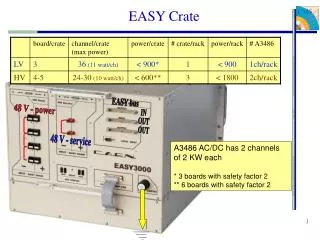
Cable Arrangement Two 50-pins are shown as one black line. Unconnected arrows of the same color and type connect to each other (one 68-pin cable per connection). Card numbers in orange, regions as hollow numbers. + Configuration for crates • = Upper 50-pin connector, J3 & = Lower 50-pin connector, J5
Operation with the MCC • Clock and Control Cards must be setup to receive a clock from the TTC. The toggle switch on the front must be in the down position (the LED should be off) • Plug in the double cable to the TTC IN Clock (lower) and TTC IN Control (upper) near the middle of the CCCs. Screw in the connectors to make good contact. • First setup the CIC using the package vmedia to execute a simple script before operation of any RCT crates: • This script will have to be updated to use the correct base address for the CIC. Currently it is e00000 (hex) - I think the card there uses f80000. • Make sure the SBS driver is installed • Subdirectory ~cmslab/MCC: • vmedia ‘read cicb_init.txt’ • This needs to only be done when the crate is turned on. • If the crate is left on, it doesn’t need to be repeated for every run.
Package Description and Use • Written as part of the package JCCTest • For data sharing test is done in two steps (then repeated for other direction) • RCTTestWithJCC -t 20 • In RCTJCC.cc doCableShareSendTest() • Function called CableShareSend.cc • File produced with all shared data (SharedData.txt) • RCTTestWithJCC -t 40 -n 10 • In RCTJCC.cc doCableShareRecvTest() • Function CableShareRecv.cc • Writes random “electron-like” data to the receiving crate • Reads in the file (SharedData.txt) with the Shared Data written to other crate • Predicts output - written to pointer and returned to RCTJCC::doCableShareRecvTest() • A reset is sent to both crates via the MCC using system() • Function EGJCC() called to read out JCC • Prediction compared to result at JCC • Repeated readout possible with -n flag (above = 10 reads of JCC)
MCC, RCT, and Reset • Reset is sent by executing a shell script resys.txt • A vmedia script is run from this shell script (I needed to change to a third CAEN controller in the MCC) • In subdirectory ~cmslab/MCC • resys.txt - vmedia script • Need to update the base address for the CIC in resys.txt • resync - performs vmedia and logs • Writes to a logfile resetlog - take care that this doesn’t get too big. • Remove CAEN environment variable • Create links to these in JCCTest directory • system() call in programs does the work • Will have change this to use ssh (slide after next) when using SBS, since will be on a separate PC • Single crate tests can be run (with J4 silencers) by using with the flag -mcc in TestCrateWithJCC.com • Look for the system() calls and update them for the SBS • Maybe get environment variables to change how this is done
Operation with the CAEN Controller • The CAENs’ PCI cards are all in one PC so I was able to script the process using environment variables to change crate control: • First top crate receives, bottom crate sends • export CAEN_LINK=0; Select bottom crate’s CAEN controller • RCTTestWithJCC -t 20; • export CAEN_LINK=1; Select top crate’s CAEN controller • RCTTestWithJCC -t 40 -n 1; MCC Reset to RCT done here • Then bottom crate receives, top crate sends • RCTTestWithJCC -t 20; • export CAEN_LINK=0; • RCTTestWithJCC -t 40 -n 1; MCC Reset to RCT done here • The reset to the MCC crate controller is integrated into a script called with system() in the RCTJCC::doCableShareRecvTest()
Operation with SBS • With the SBS, several PC’s need to be used along with ssh remote command execution. • ssh user@login command • Either in system() or in scripts • Use keys to enable “password free” login • You will have to replace some of the program calls and the CAEN_LINK environment variables
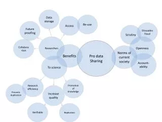
Upgrades • The whole test can probably be simplified • write all data to both crates first • then check sharing for both • Cabling should be redone as well to be more “barrel like” • Next Slide • Good idea to do this before expansion to 4 crates • Expand to 4 crates • Two possible crate arrangements • Two Eta halves, two Phis (see slide after next) • One Eta half, four Phis (see two slides after next)
Cable Configuration “Barrel” Two 50-pins are shown as black lines Unconnected arrows of the same color connect to each other (one cable) + Configuration for crates • = Upper 50-pin connector, J3 & = Lower 50-pin connector, J5
Expanding to 4 Crates Sharing between crates loops around, becomes a small “barrel” 68-pin cables shown by small double arrows and …same color arced arrows connect to each other - one 68-pin cable per pair. “Y” cables on each RC 6 for a total of 4, Short end connects to a long end 50-pin connections do not make sense in this configuration To lowest crates 4 “Y” Cables To highest crates
Expanding to 4 Crates To lowest crates – + 2 “Y” Cables 2 “Y” Cables To highest crates Similar to slide before, but now we can use 50-pin cables to share corners and left-right. The magenta cables are corner sharing and the indexes go to the same index on the other end. The black cables are the left-right sharing. A total of 8 50-pin cables will be used in this configuration. The same number of 68-pin as before. Configuration of the – crates will be slightly different, as well. TP_LF, a bit for the EISO ASIC will change.
Coming Soon • I’ll need to write something up on how I group the towers to do the electron algorithm • I’ll give you the format of the SharedData.txt, since there is some compression of data to avoid writing towers twice. • Also of the TowerPatterns.txt which is a sort of ASCII viewer to look at the patterns in the crate. • TP_LF configurations for different etas.