Download
1 / 25
250 likes | 387 Views
TOWERS CRESCENT BUILDING F Introduction. - 199’ Speculative Office Building - 304,880 Square Feet of Office Space - 368,770 Square Feet of Parking Space - Original Structural Design by KCE; Redesigned by SK&A - Hensel Phelps Construction Management - Design-Assist Project

E N D
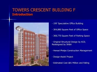
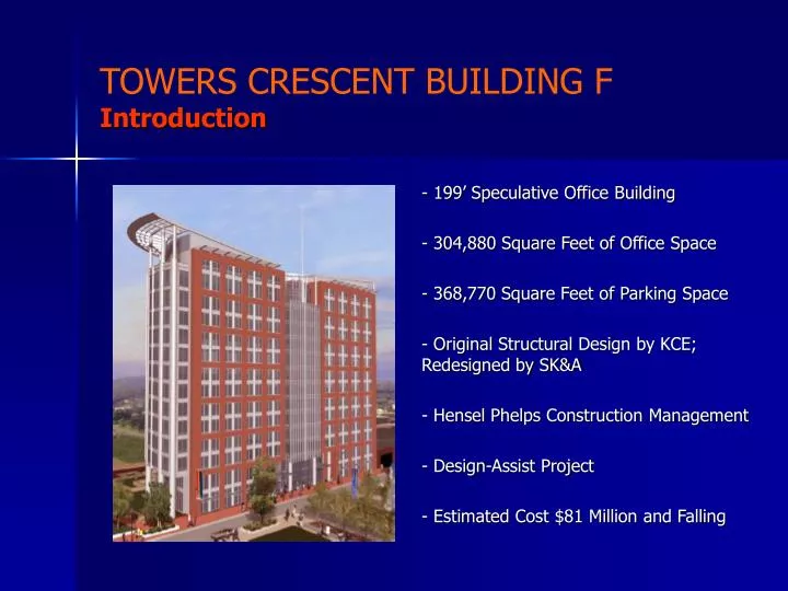
TOWERS CRESCENT BUILDING FIntroduction - 199’ Speculative Office Building - 304,880 Square Feet of Office Space - 368,770 Square Feet of Parking Space - Original Structural Design by KCE; Redesigned by SK&A - Hensel Phelps Construction Management - Design-Assist Project - Estimated Cost $81 Million and Falling
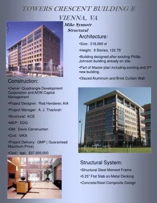
TOWERS CRESCENT BUILDING FArchitecture - Semicircular tower over subterranean parking levels - Central core area containing elevators, bathrooms, stairways, electrical and mechanical rooms, etc., otherwise open plan - Façade employs mixture of glass, stainless steel and aluminum, and brick veneer; no brick on North side - Painted steel spire and large architectural ornament which resembles metal fan spread over building. - Plaza with greenery at base of tower
TOWERS CRESCENT BUILDING FExisting Structural System Caisson Foundation, Concrete Columns, Flat Slab, Shear Walls
TOWERS CRESCENT BUILDING FFloor System Redesign - Post-tensioning investigated as means to reducing slab 8” to 6” - 24”x14” supporting edge beams to produce 1-way behavior and contribute to lateral stiffness - Columns moved, 1 added - Live load reduced from 100 psf to 70 psf
TOWERS CRESCENT BUILDING FPost-Tesnsioned Design Longitude Tendons
TOWERS CRESCENT BUILDING FPost-Tesnsioned Design Latitude Tendons
TOWERS CRESCENT BUILDING FPost-Tensioned Design - All slab areas pass - Certain beams fail, are upsized - Alleged punching shear failures and some alleged beam failures determined to be erroneous
TOWERS CRESCENT BUILDING FPost-Tensioned Design RAM Designs Reinforcement
TOWERS CRESCENT BUILDING FLateral Analysis - 3-D model represents spatial distribution of mass and stiffness in the structure - Makes use of heretofore neglected lateral stiffness elements such as curved frame - More accurate distribution of loads - Allows accurate determination of fundamental period - Introduction of edge beams stiffens structure and simplifies analysis
TOWERS CRESCENT BUILDING FLateral Analysis - Orthogonally intersecting shear walls serve as web and flange for one beam section - Mass and center of mass determined in detailed spreadsheets - Columns modeled as rectangular sections, beams as T sections - Flexural stiffness of beams reduced by 50% and walls by 30% to account for cracking
TOWERS CRESCENT BUILDING FLateral Analysis - 26” deep shear ties added between shear walls - Dramatically increases stiffness in East-West Direction by joining two sections into one section about 3x as deep - Increases torsional stiffness by providing logical path for shear flow - Requires reduction in elevator lobby ceiling height from 10’ to 9’
TOWERS CRESCENT BUILDING FSeismic Analysis Occupancy Category III - Seismic Use Group II, I = 1.25 Seismic Site Classification D Seismic design category B; ρ = 1.0 Shear wall-frame interactive system with ordinary reinforced concrete moment frames and ordinary reinforced concrete shear walls. R = 5.5; Ω = 5.5; Cd = 4.5 Spectral Response Acceleration Sds = 0.208; Sd1 = 0.112 Loads calculated by ELF, applied N-S & E-W Building passes 1.5% story drift criteria
TOWERS CRESCENT BUILDING FWind Analysis - Wind loads calculated in accordance with the provisions of ASCE 7-02 Section 6.5 for dynamic structures - Load factor of 1.6 - Applied loads at 100% strength at center of area and 75% strength at eccentricity determined by Eq 6-21 (1) North-South, non-eccentric loading: δmax = 2.69” (2) North-South, eccentric loading: δmax = 8.09” (3) East-West, non-eccentric loading: δmax = 3.24” (4) East-West, eccentric loading: δmax = 3.98”
TOWERS CRESCENT BUILDING FWind Analysis - Deflections within industry standard tolerance of l/400 except North-South eccentric loading - North-South eccentric loading deflects l/295 - Load applied in this analysis much larger than the load which would be applied in an actual windstorm, due to the 16’ perforated panel wall at the top of the structure. Code requires (ASCE 7-02, Sec. 6.5.2.2) that one treat air permeable cladding as solid wall, unless “approved test data or recognized literature demonstrate lower loads for the type of air permeable cladding being considered.” - Since dynamic structure, eccentricity of applied loading amplified by Equation 6-21. Results in eccentricity of 62.1’, which is higher than actual. - Wind tunnel test would have been helpful; currently one must treat semicurcular face of building as projected rectangle
TOWERS CRESCENT BUILDING FStrength Check - West shear wall under N-S ecc. Loading carries 1,265k shear, 67,275 ft-k overturning moment - ФVn = 0.6(5744)(2(80001/2) + 0.002045(60000)) = 1039.4k < 1264.8k (no good) - 100(4π) + 20(1)(4π) + 15(2)(4π) = 1885k < 2293.5k (no good)
TOWERS CRESCENT BUILDING FShear Tie Design - Critical tie beam load applied to bottom tie beam of the second floor under East-West eccentric wind loading - Maximum moment 521 ft-k, maximum shear 120k; above design resists 512 ft-k moment, 120k shear
TOWERS CRESCENT BUILDING FColumns and Foundations - Reduction in weight allows reduction in column and caisson sizes - Consider 1.2D+1.6L+0.5S and 1.2D+1.0L+1.6W+0.5S - Column 34 currently specified as 24”x24” section roof to 4th floor, 24”x30” section from 4th floor to level P4, 24”x36”section from P4 to the base - PCA Column shows 18”x24” w/ (12) #9 vertical reinforcing rods suffices to 4th floor, 24”x24” w/ (12) #10 suffices to base - Caisson could not be reduced
TOWERS CRESCENT BUILDING FArchitectural Design Rose, black, and white granite
TOWERS CRESCENT BUILDING FMechanical Adjustments - Reshape ducts so as not to increase frictional losses De = 1.3(ab)5/8/(a + b)1/4 = 1.3(12*12)5/8/(12 + 12)1/4 = 13.12 = 1.3(10 *b)5/8/(10 + b)1/4 b = 15” De = 1.3(16*10)5/8/(16 + 10)1/4 = 13.73 = 1.3(8 * b)5/8/(8 + b)1/4 b = 21” De = 1.3(14*12)5/8/(14 + 12)1/4 = 14.16 = 1.3(9 * b)5/8/(9 + b)1/4 b = 20”
TOWERS CRESCENT BUILDING FDiscussion and Recommendations - Laying out post-tensioning difficult due to irregular floor plan; results are only moderately successful - Reduction of slab from 8” to 6” saves materials expenses - Benefit would be offset by additional labor and time of construction required to build post-tensioned slab - Was not able to reduce floor to floor height - In some places I have had to make the floor system deeper - Weighing advantages and disadvantages of my post-tensioned slab against current conventional reinforced slab, current system better
TOWERS CRESCENT BUILDING FDiscussion and Recommendations - Do recommend the addition of shear tie beams to connect the shear walls in the East-West direction - Shear ties will dramatically increase the stiffness of this building in the East-West direction - Adding these small members allow large reductions in the size of the lateral system elsewhere - Unfortunately, not able to prove this; SK&A must have determined the stiffness of the structure more rigorously, and hence less conservatively, than I - According to my calculations, structure fails deflection criterion (maximum building deflection under eccentric wind loading in the North-South direction) even with addition of shear ties - Also, in my calculations, one wall, with the caissons underneath it, fails strength criteria
TOWERS CRESCENT BUILDING FDiscussion and Recommendations - Wind tunnel testing would be helpful; would decrease one particular load (eccentric North-South wind load) which is especially conservative, and which is greatest impediment to downsizing lateral system - Performance of this test, combined with addition of shear ties and more rigorous determination of building stiffness, would allow reduction in thickness of shear walls and thus achieve significant materials savings - Also, would recommend decreasing live load on office floor from 100 psf to 70 psf, which would make it possible to downsize columns - Furthermore, would recommend more rigorous analysis of bearing capacity of caissons - Current stipulation of the plans, caissons designed “for an allowable bearing pressure of 100,000 psf plus skin friction of 1,000 psf between elevation 440.00’ and 420.00’, and 2,000 psf for elevation below 420.00” - Allowable stresses could be determined more accurately by a number of accepted theoretical and empirical methods
TOWERS CRESCENT BUILDING FAcknowledgements Dr. Boothby, Dr. Lepage, Cynthia Milinichik, Joe Uchno, John Logue