Download
1 / 54
550 likes | 839 Views
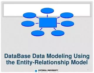
Chapter 2: Entity-Relationship Model. Entity Sets Relationship Sets Design Issues Mapping Constraints Keys E-R Diagram Extended E-R Features Design of an E-R Database Schema Reduction of an E-R Schema to Tables. Entity Sets. A database can be modeled as: a collection of entities,

E N D
Chapter 2: Entity-Relationship Model • Entity Sets • Relationship Sets • Design Issues • Mapping Constraints • Keys • E-R Diagram • Extended E-R Features • Design of an E-R Database Schema • Reduction of an E-R Schema to Tables
Entity Sets • A database can be modeled as: • a collection of entities, • relationship among entities. • An entity is an object that exists and is distinguishable from other objects. • Example: specific person, company, event, plant • Entities have attributes • Example: people have names and addresses • An entity set is a set of entities of the same type that share the same properties. • Example: set of all persons, companies, trees, holidays
Entity Sets customer and loan customer-id customer- customer- customer- loan- amount name street city number
Attributes • An entity is represented by a set of attributes, that is descriptive properties possessed by all members of an entity set. • Domain – the set of permitted values for each attribute • Attribute types: • Simple and composite attributes. • Single-valued and multi-valued attributes • E.g. multivalued attribute: phone-numbers • Derived attributes • Can be computed from other attributes • E.g. age, given date of birth Example: customer = (customer-id, customer-name, customer-street, customer-city) loan = (loan-number, amount)
Relationship Sets • A relationship is an association among several entities Example:HayesdepositorA-102customer entity relationship set account entity • A relationship set is a mathematical relation among n 2 entities, each taken from entity sets {(e1, e2, … en) | e1 E1, e2 E2, …, en En}where (e1, e2, …, en) is a relationship • Example: (Hayes, A-102) depositor
Relationship Sets (Cont.) • An attribute can also be property of a relationship set. • For instance, the depositor relationship set between entity sets customer and account may have the attribute access-date
Degree of a Relationship Set • Refers to number of entity sets that participate in a relationship set. • Relationship sets that involve two entity sets are binary (or degree two). Generally, most relationship sets in a database system are binary. • Relationship sets may involve more than two entity sets. • Relationships between more than two entity sets are rare. Most relationships are binary. (More on this later.) • E.g. Suppose employees of a bank may have jobs (responsibilities) at multiple branches, with different jobs at different branches. Then there is a ternary relationship set between entity sets employee, job and branch
Mapping Cardinalities • Express the number of entities to which another entity can be associated via a relationship set. • Most useful in describing binary relationship sets. • For a binary relationship set the mapping cardinality must be one of the following types: • One to one • One to many • Many to one • Many to many
Mapping Cardinalities One to one One to many Note: Some elements in A and B may not be mapped to any elements in the other set
Mapping Cardinalities Many to one Many to many Note: Some elements in A and B may not be mapped to any elements in the other set
Mapping Cardinalities affect ER Design • Can make access-date an attribute of account, instead of a relationship attribute, if each account can have only one customer • I.e., the relationship from account to customer is many to one, or equivalently, customer to account is one to many
E-R Diagrams • Rectangles represent entity sets. • Diamonds represent relationship sets. • Lines link attributes to entity sets and entity sets to relationship sets. • Ellipses represent attributes • Double ellipses represent multivalued attributes. • Dashed ellipses denote derived attributes. • Underline indicates primary key attributes (will study later)
E-R Diagram With Composite, Multivalued, and Derived Attributes
Roles • Entity sets of a relationship need not be distinct • The labels “manager” and “worker” are called roles; they specify how employee entities interact via the works-for relationship set. • Roles are indicated in E-R diagrams by labeling the lines that connect diamonds to rectangles. • Role labels are optional, and are used to clarify semantics of the relationship
Cardinality Constraints • We express cardinality constraints by drawing either a directed line (), signifying “one,” or an undirected line (—), signifying “many,” between the relationship set and the entity set. • E.g.: One-to-one relationship: • A customer is associated with at most one loan via the relationship borrower • A loan is associated with at most one customer via borrower
One-To-Many Relationship • In the one-to-many relationship a loan is associated with at most one customer via borrower, a customer is associated with several (including 0) loans via borrower
Many-To-One Relationships • In a many-to-one relationship a loan is associated with several (including 0) customers via borrower, a customer is associated with at most one loan via borrower
Many-To-Many Relationship • A customer is associated with several (possibly 0) loans via borrower • A loan is associated with several (possibly 0) customers via borrower
Participation of an Entity Set in a Relationship Set • Totalparticipation (indicated by double line): every entity in the entity set participates in at least one relationship in the relationship set • E.g. participation of loan in borrower is total • every loan must have a customer associated to it via borrower • Partial participation: some entities may not participate in any relationship in the relationship set • E.g. participation of customer in borrower is partial
Alternative Notation for Cardinality Limits • Cardinality limits can also express participation constraints
Keys • A super key of an entity set is a set of one or more attributes whose values uniquely determine each entity. • A candidate key of an entity set is a minimal super key • Customer-id is candidate key of customer • account-number is candidate key of account • Although several candidate keys may exist, one of the candidate keys is selected to be the primary key.
Keys for Relationship Sets • The combination of primary keys of the participating entity sets forms a super key of a relationship set. • (customer-id, account-number) is the super key of depositor • NOTE: this means a pair of entity sets can have at most one relationship in a particular relationship set. • E.g. if we wish to track all access-dates to each account by each customer, we cannot assume a relationship for each access. We can use a multivalued attribute though • Must consider the mapping cardinality of the relationship set when deciding the what are the candidate keys • Need to consider semantics of relationship set in selecting the primary key in case of more than one candidate key
Binary Vs. Non-Binary Relationships • Some relationships that appear to be non-binary may be better represented using binary relationships • E.g. A ternary relationship parents, relating a child to his/her father and mother, is best replaced by two binary relationships, father and mother • Using two binary relationships allows partial information (e.g. only mother being know) • But there are some relationships that are naturally non-binary • E.g. works-on
Converting Non-Binary Relationships to Binary Form • In general, any non-binary relationship can be represented using binary relationships by creating an artificial entity set. • Replace R between entity sets A, B and Cby an entity set E, and three relationship sets: 1. RA, relating E and A 2.RB, relating E and B 3. RC, relating E and C • Create a special identifying attribute for E • Add any attributes of R to E • For each relationship (ai , bi , ci) in R, create 1. a new entity eiin the entity set E 2. add (ei , ai ) to RA 3. add (ei , bi) to RB 4. add (ei , ci ) to RC
Design Issues • Use of entity sets vs. attributesChoice mainly depends on the structure of the enterprise being modeled, and on the semantics associated with the attribute in question. • Use of entity sets vs. relationship setsPossible guideline is to designate a relationship set to describe an action that occurs between entities • Binary versus n-ary relationship setsAlthough it is possible to replace any nonbinary (n-ary, for n > 2) relationship set by a number of distinct binary relationship sets, a n-ary relationship set shows more clearly that several entities participate in a single relationship. • Placement of relationship attributes
Weak Entity Sets • An entity set that does not have a primary key is referred to as a weak entity set. • The existence of a weak entity set depends on the existence of a identifying entityset • it must relate to the identifying entity set via a total, one-to-many relationship set from the identifying to the weak entity set • Identifying relationship depicted using a double diamond • The discriminator (or partial key) of a weak entity set is the set of attributes that distinguishes among all the entities of a weak entity set. • The primary key of a weak entity set is formed by the primary key of the strong entity set on which the weak entity set is existence dependent, plus the weak entity set’s discriminator.
Weak Entity Sets (Cont.) • We depict a weak entity set by double rectangles. • We underline the discriminator of a weak entity set with a dashed line. • payment-number – discriminator of the payment entity set • Primary key for payment – (loan-number, payment-number)
Weak Entity Sets (Cont.) • Note: the primary key of the strong entity set is not explicitly stored with the weak entity set, since it is implicit in the identifying relationship. • If loan-number were explicitly stored, payment could be made a strong entity, but then the relationship between payment and loan would be duplicated by an implicit relationship defined by the attribute loan-number common to payment and loan
More Weak Entity Set Examples • In a university, a course is a strong entity and a course-offering can be modeled as a weak entity • The discriminator of course-offering would be semester (including year) and section-number (if there is more than one section) • If we model course-offering as a strong entity we would model course-number as an attribute. Then the relationship with course would be implicit in the course-number attribute
Specialization • Top-down design process; we designate subgroupings within an entity set that are distinctive from other entities in the set. • These subgroupings become lower-level entity sets that have attributes or participate in relationships that do not apply to the higher-level entity set. • Depicted by a triangle component labeled ISA (E.g. customer “is a” person). • Attribute inheritance – a lower-level entity set inherits all the attributes and relationship participation of the higher-level entity set to which it is linked.
Generalization • A bottom-up design process – combine a number of entity sets that share the same features into a higher-level entity set. • Specialization and generalization are simple inversions of each other; they are represented in an E-R diagram in the same way. • The terms specialization and generalization are used interchangeably.
Specialization and Generalization (Contd.) • Can have multiple specializations of an entity set based on different features. • E.g. permanent-employee vs. temporary-employee, in addition to officer vs. secretary vs. teller • Each particular employee would be • a member of one of permanent-employee or temporary-employee, • and also a member of one of officer, secretary, or teller • The ISA relationship also referred to as superclass - subclass relationship
Design Constraints on a Specialization/Generalization • Constraint on which entities can be members of a given lower-level entity set. • condition-defined • E.g. all customers over 65 years are members of senior-citizen entity set; senior-citizen ISA person. • user-defined • Constraint on whether or not entities may belong to more than one lower-level entity set within a single generalization. • Disjoint • an entity can belong to only one lower-level entity set • Noted in E-R diagram by writing disjoint next to the ISA triangle • Overlapping • an entity can belong to more than one lower-level entity set
Design Constraints on a Specialization/Generalization (Contd.) • Completenessconstraint -- specifies whether or not an entity in the higher-level entity set must belong to at least one of the lower-level entity sets within a generalization. • total: an entity must belong to one of the lower-level entity sets • partial: an entity need not belong to one of the lower-level entity sets
E-R Design Decisions • The use of an attribute or entity set to represent an object. • Whether a real-world concept is best expressed by an entity set or a relationship set. • The use of a ternary relationship versus a pair of binary relationships. • The use of a strong or weak entity set. • The use of specialization/generalization – contributes to modularity in the design. • The use of aggregation – can treat the aggregate entity set as a single unit without concern for the details of its internal structure.
Reduction of an E-R Schema to Tables • Primary keys allow entity sets and relationship sets to be expressed uniformly as tables which represent the contents of the database. • A database which conforms to an E-R diagram can be represented by a collection of tables. • For each entity set and relationship set there is a unique table which is assigned the name of the corresponding entity set or relationship set. • Each table has a number of columns (generally corresponding to attributes), which have unique names. • Converting an E-R diagram to a table format is the basis for deriving a relational database design from an E-R diagram.
Representing Entity Sets as Tables • A strong entity set reduces to a table with the same attributes.
Composite and Multivalued Attributes • Composite attributes are flattened out by creating a separate attribute for each component attribute • E.g. given entity set customer with composite attribute name with component attributes first-name and last-name the table corresponding to the entity set has two attributesname.first-name and name.last-name • A multivalued attribute M of an entity E is represented by a separate table EM • Table EM has attributes corresponding to the primary key of E and an attribute corresponding to multivalued attribute M • E.g. Multivalued attribute dependent-names of employee is represented by a tableemployee-dependent-names( employee-id, dname) • Each value of the multivalued attribute maps to a separate row of the table EM • E.g., an employee entity with primary key John and dependents Johnson and Johndotir maps to two rows: (John, Johnson) and (John, Johndotir)
Representing Weak Entity Sets • A weak entity set becomes a table that includes a column for the primary key of the identifying strong entity set
Representing Relationship Sets as Tables • A many-to-many relationship set is represented as a table with columns for the primary keys of the two participating entity sets, and any descriptive attributes of the relationship set. • E.g.: table for relationship set borrower
Redundancy of Tables • Many-to-one and one-to-many relationship sets that are total on the many-side can be represented by adding an extra attribute to the many side, containing the primary key of the one side • E.g.: Instead of creating a table for relationship account-branch, add an attribute branch to the entity set account