Download
1 / 72
750 likes | 918 Views
Computational thermal-Fluid-Dynamics (CtFD) Issues in Nuclear Fusion Reactors. R. Zanino, S. Giors, L. Savoldi Richard, F. Subba Dipartimento di Energetica, Politecnico, Torino, Italy. Outline. Introduction Selected topics:

E N D
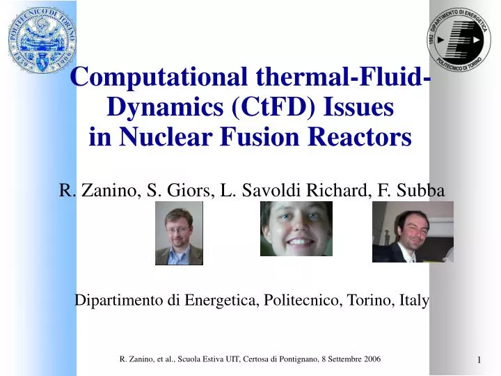
R. Zanino, et al., Scuola Estiva UIT, Certosa di Pontignano, 8 Settembre 2006 Computational thermal-Fluid-Dynamics (CtFD) Issues in Nuclear Fusion Reactors R. Zanino, S. Giors, L. Savoldi Richard, F. Subba Dipartimento di Energetica, Politecnico, Torino, Italy
R. Zanino, et al., Scuola Estiva UIT, Certosa di Pontignano, 8 Settembre 2006 Outline • Introduction • Selected topics: • Physics: Modeling plasma-surface interactions (PSI) in tokamaks CODEDEVELOPMENT only • Magnet Technology: Modeling cable-in-conduit conductors (CICC) for the superconducting ITER coils CODEDEVELOPMENT + FLUENT • Vacuum Technology: Modeling Turbo-Molecular Pumps (TMP) FLUENT only • Conclusions and perspective
R. Zanino, et al., Scuola Estiva UIT, Certosa di Pontignano, 8 Settembre 2006 Introduction (I): Nuclear fusion • Conditions: magnetically confine in a volume (~ 102-103 m3), for a sufficiently long time, a mixture (plasma = fully ionized gas) of deuterium (D) and tritium (T) with density ~ 1020-1021 m-3 and temperature ~ 10-20 keV Potential: (almost) clean and unlimitedenergy!! • Aim: realize a sufficient amount of nuclear fusion reactions 2D + 3T n (14.1 MeV) + 4He (3.5 MeV) Heats the blanket Thermal energy Electric power Heats the plasma Ignition
R. Zanino, et al., Scuola Estiva UIT, Certosa di Pontignano, 8 Settembre 2006 Components of a tokamak fusion reactor • V = vacuum chamber, • PI = pellet injector, NBI = neutral beam injector, • FW = first wall, DP = divertor plate, • A = antenna for auxiliary plasma heating, • B = blanket, • Magnet system: CS = central solenoid, TF = toroidal field coil, PF = poloidal field coil, • C = cryostat, • SG = steam generator, T = turbine. Vertical cross section through symmetry axis (sketch)
R. Zanino, et al., Scuola Estiva UIT, Certosa di Pontignano, 8 Settembre 2006 Introduction (II): ITER • ITER tokamak construction approved June 2005 • 10 GEuro project: 50 % EU, 50 % (JA, RF, US, CN, KO, IN) • Reactor site Cadarache (F) • 10 year construction (start 2007) + 20 year operation
R. Zanino, et al., Scuola Estiva UIT, Certosa di Pontignano, 8 Settembre 2006 Tokamaks: generalities Toroidal geometry Transformer principle Poloidal magnetic field generated by plasma current Complex magnetic field assembly for confining and controlling the plasma
R. Zanino, et al., Scuola Estiva UIT, Certosa di Pontignano, 8 Settembre 2006 Introduction (IV): ITER goals • Achieve inductive plasma burn with amplification factor Q = generated/injected power of at least 5-10; • Possibility of controlled ignition (Q ) not precluded • Integrate the technologies essential for a fusion reactor (e.g. superconducting magnets, remote maintenance); • Test components for a future reactor (e.g. divertor and torus vacuum pumps); • Test tritium breeding module concepts for DEMO.
R. Zanino, et al., Scuola Estiva UIT, Certosa di Pontignano, 8 Settembre 2006 PSI in tokamaks: Geometry Scrape-off layer (SOL) (“open” magnetic surfaces) Limiter/First Wall Main plasma (closed magnetic surfaces) • Toroidal symmetry edge plasma problem is 2D : • radial r (across magnetic surfaces) • poloidal (around “small” torus circumference) Divertorplates
R. Zanino, et al., Scuola Estiva UIT, Certosa di Pontignano, 8 Settembre 2006 PSI in tokamaks: Physics Plasma confinement is never perfect because of dissipation The plasma interacts with the solid walls Heat load peaks up to tens of MW/m2 Possible serious damage of plasma facing components (walls) Lifetime issue Radiation from the plasma edge in a first-wall/limiter tokamak Immission of impurities from the walls into the plasma (e.g.. C in the case of graphite walls) Erosion of the walls but also radiation from ionized impurities possible switch-off of fusion reactions. Radiation from the plasma edge in a divertor tokamak
R. Zanino, et al., Scuola Estiva UIT, Certosa di Pontignano, 8 Settembre 2006 Plasma-Boundary electrostatic sheath Ions: large mass, low speed Wall Electrons: small mass, high speed Random motion electric wall current charge accumulation electrostatic sheath ni profile ne profile Particle flux n = ncs (not zero!!!) Wall Energy flux E = n main plasma ~ 8 (Ion + Electron contribution) sheath D~ 10-5 m
Cosine Model n SOL B wall L = Connection length (distance between walls) MAIN PLASMA From continuity: Heat flux on the wall making a finite angle with B: R. Zanino, et al., Scuola Estiva UIT, Certosa di Pontignano, 8 Settembre 2006
Power balance considerations (Lawson Criterion with impurities) Output (losses):Pout = PL + PR PL = 3nT/E Conduction/convection PR = n nz (T,Z) Impurity radiation losses Input:Pin Pin = n2/4<V>E From fusion reactions IGNITION (= self-sustained reaction): Pin Pout Limitation on the tolerable radiation from impurities PR ~ nz (T,Z) CHOICE OF MATERIAL! R. Zanino, et al., Scuola Estiva UIT, Certosa di Pontignano, 8 Settembre 2006
R. Zanino, et al., Scuola Estiva UIT, Certosa di Pontignano, 8 Settembre 2006 PSI in tokamaks: Modeling issues • Fluid vs. kinetic plasma (10-7 < Kn mfp/L < 101 range achieved in SOL!) • Complicating physics/geometry issues • Multi-fluid (1 fluid = 1 ionization stage) for impurities, e.g., 6 fluids for C but, in principle, 74 fluids for W! • Presence of non-magnetized, kinetic neutral particles Sources Monte-Carlo approach typically adopted • Treatment of third (diamagnetic) direction (drifts, etc.) • Lack of consolidated fundamental knowledge on some issues • Radial “anomalous” transport most often adopt diffusive Ansatz • Boundary conditions (Debye sheath, etc) • Atomic physics database available (for some materials)
R. Zanino, et al., Scuola Estiva UIT, Certosa di Pontignano, 8 Settembre 2006 PSI in tokamaks: Fluid (Braginskii) plasma model Sources from plasma-neutral interactions • j = i, e (pure plasma) • Complete Navier-Stokes solved only along magnetic field B
R. Zanino, et al., Scuola Estiva UIT, Certosa di Pontignano, 8 Settembre 2006 PSI in tokamaks: Computational issues • Huge transport anisotropy: Vr << V, r << SOL thickness << SOL length Stretched grid with very good alignment in is needed! • Strong gradients from localized sources (adaptivity needed, …) • Strong nonlinearities (transport coefficients along B T5/2, radiation/atomic physics rates (exponential), …) • Different physical processes involved Often need to couple intrinsically different numerical approaches (e.g. CFD + Monte Carlo) PROBLEM BEYOND CAPABILITIES OF STANDARD COMMERCIAL CODES DEVELOPMENT NEEDED!
R. Zanino, et al., Scuola Estiva UIT, Certosa di Pontignano, 8 Settembre 2006 PSI in tokamaks: Numerical methods (I) -- FV • FV were historically the first method adopted for CFD edge plasma modeling • A number of widely used tools exists today • 5-point molecule (B2) • 9-point molecule (UEDGE and EDGE2D) based on quadrilateral meshes optimized for divertor • Increasingly complex physical/numerical ingredients added by many contributors over more than 20 years • Areas of active research development: • Other geometries besides divertor First Wall/Limiter • Adaptive grid methods • Some physics models are still not validated
R. Zanino, et al., Scuola Estiva UIT, Certosa di Pontignano, 8 Settembre 2006 PSI in tokamaks: Results (I) FV multi-fluid model of ASDEX Upgrade divertor Computed (B2-Eirene) vs. measured radiation intensity Tomographic reconstruction Profiles at the target
R. Zanino, et al., Scuola Estiva UIT, Certosa di Pontignano, 8 Settembre 2006 PSI in tokamaks: Numerical methods (II) -- FE • First attempt at dealing with realistic geometries (early-to-mid ’90s) • Extended to use adaptive grids (late ’90s) • Adaptive triangular grid generator written by INRIA [H. Bourouchaki et al] coupled with model electron heat advection/diffusion/radiation Finite Element solver • Mesh size and alignment controlled by locally defining the 2D metric • Mesh alignment guaranteed within a few degrees • Conservation issue (see below)
R. Zanino, et al., Scuola Estiva UIT, Certosa di Pontignano, 8 Settembre 2006 PSI in tokamaks: Results (II) FE model of ASDEX Upgrade divertor AD BC n Te Ti Relatively slow convergence likely due to non conservation on finite grid
R. Zanino, et al., Scuola Estiva UIT, Certosa di Pontignano, 8 Settembre 2006 PSI in tokamaks: Results (IIa) FE model of scalar problems in divertor geometry Anisotropic diffusion Adaptive grids Anisotropic advection
R. Zanino, et al., Scuola Estiva UIT, Certosa di Pontignano, 8 Settembre 2006 PSI in tokamaks: Numerical methods (III) -- CVFE • Most recent attempt at dealing with complex geometries while still guaranteeing conservation • Adopt triangular meshes. Force one element side to be always aligned with the B field • Employ the Control-Volume Finite-Element technique to guarantee conservation on every finite-size mesh • Segregated approach to couple continuity-momentum-energy equations • First single-fluid application proved effective on the difficult (= previously untackled) First-Wall/Limiter geometry
R. Zanino, et al., Scuola Estiva UIT, Certosa di Pontignano, 8 Settembre 2006 PSI in tokamaks: Numerical methods (IIIa) -- CVFE B B
R. Zanino, et al., Scuola Estiva UIT, Certosa di Pontignano, 8 Settembre 2006 V// [m/s] @ Top region Z [m] 0.90 6.4e4 0.88 0.86 3.2e4 0.84 0.82 3.2e2 0.80 0.78 -3.1e4 0.76 7.85 -6.3e4 0.74 7.80 0.72 1.05 0.95 1.10 R [m] 1.00 7.75 Particles [1020´s-1] 7.70 Mesh-independent value, estimated by Richardson extrapolation 7.65 7.60 200 400 600 800 1000 1200 1400 Number of nodes PSI in tokamaks: Results (III) CVFE model of IGNITOR first wall/limiter Spatial convergence tests on simple model problems were satisfactory CVFE show good performance in regions where quadrilateral meshes would be too distorted
R. Zanino, et al., Scuola Estiva UIT, Certosa di Pontignano, 8 Settembre 2006 ITER superconducting magnet system (I)
R. Zanino, et al., Scuola Estiva UIT, Certosa di Pontignano, 8 Settembre 2006 Current lead 80kA Current lead 80kA Cryostat Extension Bus bar type1 Bus bar type2 TF-model coil (TFMC) Inter-coil structure (ICS) Vacuum vessel Magnet windings PANCAKE WOUND LAYER WOUND
R. Zanino, et al., Scuola Estiva UIT, Certosa di Pontignano, 8 Settembre 2006 CICC for ITER superconducting coils SC coils for fusion applications (e.g., ITER) carry high currents (up to ~ 70-80 kA) to generate high magnetic fields (up to ~ 13 T) Low critical temperature SC (e.g., Nb3Sn or NbTi) are used in multi-stage cable-in-conduit conductors (CICC) cooled by supercritical He @ ~ 5 K and 0.5 MPa
R. Zanino, et al., Scuola Estiva UIT, Certosa di Pontignano, 8 Settembre 2006 Thermophysical Properties of Materials in Cryogenic Conditions ·Solids • Super-conductors (e.g., Nb3Sn, NbTi) • Conductors (Cu) • Structural (SS, Incoloy, Ti) ·Fluids • He
R. Zanino, et al., Scuola Estiva UIT, Certosa di Pontignano, 8 Settembre 2006 CICC for ITER: Modeling issues • Conductor must be kept below critical temperature capability to reproduce/predict thermal-hydraulic transient: • Heat slug propagation • Stability • Quench propagation • … • Absence of diagnostics inside the conductors/magnets the conductor performance must be reliably extract from “global” (=inlet, outlet) measurements (T, dm/dt, p, V, I,…) • The level of detail needed in the TH analysis (global vs. local analysis, …) is function of the nature of the problem (slow vs. fast transient, …) and of the SC type (Nb3Sn vs. NbTi)
R. Zanino, et al., Scuola Estiva UIT, Certosa di Pontignano, 8 Settembre 2006 CICC for ITER: Computational issues • Multi-physics (TH + EM + ME) nature of the problem • Timescales: 10-3 s 102 s • Length scales: 10-6 m 102 m • Complex structure of the cable bundle • Complex interaction between cable constituents
R. Zanino, et al., Scuola Estiva UIT, Certosa di Pontignano, 8 Settembre 2006 CICC for ITER : Models (I) – Global 1D thermal-hydraulics • Length ~ 102 m >> Diameter ~ 10-1-10-2 m 1D model • Compressible Euler-like flow ofat least two fluid components: supercritical He (~ 5 K, 0.5 MPa) in annulus voids and in central channel • Heat conduction along at least two solid components: strands (SC + Cu)andjacket /conduit (SS, Incoloy, Ti, ...) • External (cryogenic) circuit model to provide “boundary conditions” in predictive simulations • Transverse coupling inside or between CICC, possibly through structures, requires Multi-conductor and/or Multi-dimensional model
R. Zanino, et al., Scuola Estiva UIT, Certosa di Pontignano, 8 Settembre 2006 CICC for ITER : Single-conductor model(Mithrandir code) RHS sources/sinks ( interaction with solids and other channels) include constitutive relations which require transport coefficients (friction factors, heat transfer coefficients) Local 3D models
R. Zanino, et al., Scuola Estiva UIT, Certosa di Pontignano, 8 Settembre 2006 CICC for ITER : Models (II) – Local thermal-hydraulics • Recent idea: derive from local 3D models the constitutive relations for the radial transport fluxes to be used in global 1D models • The commercial FLUENT code is used for 3D analysis • Different issues could be addressed: • Friction in the central channel • Friction in the annular region (?) • Friction/heat transfer coupling in the central channel • Mass transfer between central channel and annular region • …
R. Zanino, et al., Scuola Estiva UIT, Certosa di Pontignano, 8 Settembre 2006 CICC for ITER: Local CtFD model equations (1) • Water and Air simulated @ 104 < Re < 106, hydrodynamic similarity envisaged for supercritical Helium • Incompressible Reynolds-Averaged Navier-Stokes (RANS) equations, with constant temperature and transport properties are used: • Linear energy equation, based on Reynolds analogy between turb. conduction and turbulent momentum transfer, solved for heat transfer problem: • 2-layer k- model [Chen&Patel, AIAA J. (1988)] established as best choice closure for flow with separation in 2D [Arman&Rabas, NHTA (1994)], and confirmed in 3D [RZ, SG & RM, ACE (2006)] CLOSURE REQUIRED!
R. Zanino, et al., Scuola Estiva UIT, Certosa di Pontignano, 8 Settembre 2006 y If y+ > 1 enhanced wall functions If y+ < 1 2-layer k- model yC WALL CICC for ITER: Local CtFD model equation (2): FLUENT Enhanced Wall treatment: For Rey> 200 standard k- model (fully turb. region) 2-layer k-model: For Rey < 200 one-equation model of Wolfstein (Viscosity-affected region) t and are smoothly blended between turbulent and viscosity affected regions, to avoid discontinuity across Rey=200 In the viscosity affected region only Mass, Momentum, k and (if needed) Energy conservation eqs. are solved for. Then t and follow (after Wolfstein):
R. Zanino, et al., Scuola Estiva UIT, Certosa di Pontignano, 8 Settembre 2006 WALL IN OUT z L AXIS CICC for ITER : Local CtFD model equation (3) BOUNDARY CONDITIONS: WALL: IN-OUT: Periodicity on: Given Tbulk,in Given dm/dt (or viceversa) AXIS (2D only): • SOLUTION • Finite Volume discretization, with second order upwind convective fluxes and SIMPLE linearization of pressure-momentum-turbulence equations (solution by FLUENT commercial code) • Incompressible, constant properties fluid linear energy equation is solved after the flow field solution is converged
R. Zanino, et al., Scuola Estiva UIT, Certosa di Pontignano, 8 Settembre 2006 CICC for ITER: Results (IIa) Friction in the central channel results Unstructured hybrid mesh • hexahedral in the gap and wall boundary layer • tetrahedral in the core CFD-based predictive correlation derived Validation Experimental validation Re
R. Zanino, et al., Scuola Estiva UIT, Certosa di Pontignano, 8 Settembre 2006 CICC for ITER: Results (IIb) Shear stress w g/h = 4 RECIRCULATION Cf Main/core flow g/h = 8 RE-ATTACHMENT 2D effect [Webb et al., IJHMT (1971)] recovered in 3D!
R. Zanino, et al., Scuola Estiva UIT, Certosa di Pontignano, 8 Settembre 2006 SIMPLE convergence example Din =6 mm, g=8 mm, Re=8104, fields pre-initialized with a coarser mesh solution Evolution of , for a given dm/dt CONVERGENCE CRITERIA: Variation of relative to asymptotic value < 2% In this case, ~ 2000 SIMPLE iterations would have been enough
R. Zanino, et al., Scuola Estiva UIT, Certosa di Pontignano, 8 Settembre 2006 CICC for ITER: Results (IIc) Friction in the cable bundle 3 3x19 Axial flow contours 33x7 33x7 Validation ITER TFMC 3x3x5x4x6 Compute permeability of complex cable patterns?!
R. Zanino, et al., Scuola Estiva UIT, Certosa di Pontignano, 8 Settembre 2006 Friction in porous media Darcy Forchheimer 3D Seepage velocity 1D flow velocity Permeability (m2) Inertial constant Friction factor Reynolds number
R. Zanino, et al., Scuola Estiva UIT, Certosa di Pontignano, 8 Settembre 2006 D p h p/h=10 h/D=0.04 CICC for ITER: Results (IId) Heat exchange in 2D rib roughened tube: Validation St = Nu/Re Pr • Presented numerical results are grid independent • Very good agreement of friction factor • Acceptable agreement of St, slightly better for air (Pr=0.71) than for water (Pr=5.1)
R. Zanino, et al., Scuola Estiva UIT, Certosa di Pontignano, 8 Settembre 2006 CICC for ITER: (local) results (IIe) Pr=5.1 (water) Re=105 Reattachment Streamlines Temperature contours (K)
R. Zanino, et al., Scuola Estiva UIT, Certosa di Pontignano, 8 Settembre 2006 Pr=5.1 Re=105 CICC for ITER: (local) results (IIf) Colburn-like analogy between global f and St, is not verified owing to the strong contribution to f of form drag vs. friction drag, which does not have any analogy in heat transfer Computed Reynolds/Colburn local analogy between momentum and heat transfer is not verified
CICC for ITER: Heat slug propagation (I) Nb3Sn conductor TH test&analysis (1997) 2-fluid code needed to reproduce T evolution @ different sensors bundle-hole heat diffusion For the average temperature, under suitable assumptions: Taylor-Aris dispersion R. Zanino, et al., Scuola Estiva UIT, Certosa di Pontignano, 8 Settembre 2006
R. Zanino, et al., Scuola Estiva UIT, Certosa di Pontignano, 8 Settembre 2006 CICC for ITER: Quench propagation (I) Quench propagation Cryogenic circuit Nb3Sn conductor test&analysis (1997)
R. Zanino, et al., Scuola Estiva UIT, Certosa di Pontignano, 8 Settembre 2006 ITER : Model coils – CSMC & TFMC
R. Zanino, et al., Scuola Estiva UIT, Certosa di Pontignano, 8 Settembre 2006 ITER : Insert coils – CSIC & TFCI
R. Zanino, et al., Scuola Estiva UIT, Certosa di Pontignano, 8 Settembre 2006 CICC for ITER: Stability Stability tests on the CS Insert Coil (JAERI Naka, Japan, 2000) Nb3Sn conductor test&analysis (2000) Stability margin vs dm/dt Stability margin vs T margin
R. Zanino, et al., Scuola Estiva UIT, Certosa di Pontignano, 8 Settembre 2006 CICC for ITER: Quench propagation (II) Nb3Sn conductor test&analysis (2000, 2001) CS Insert Coil tests (JAERI Naka, Japan, 2000) TF Conductor Insert tests (JAERI Naka, Japan, 2002) Propagation of quench front
R. Zanino, et al., Scuola Estiva UIT, Certosa di Pontignano, 8 Settembre 2006 CICC for ITER : Multi-conductor model(M&M code) Time scale separation along and across CICC solve 3D problem as several coupled 1D problems. Use Mithrandir model for each CICC Transverse coupling is explicit in time Longitudinal coupling with circuit code Very general coil topology can be simulated with this strategy!