Download
1 / 23
230 likes | 384 Views
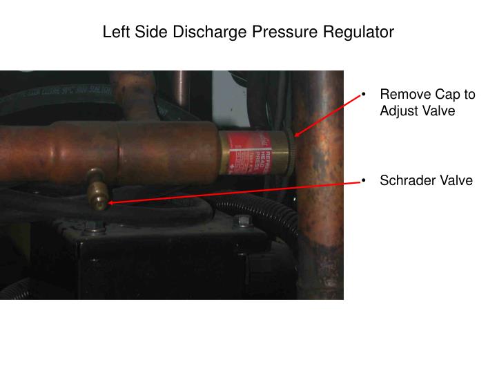
Left Side Discharge Pressure Regulator. Remove Cap to Adjust Valve Schrader Valve. Adjusting Discharge Pressure Regulating Valve. Unit must be on defrost for adjustment of setting Proper setting for R404a is ~ 240 to 270 psig Use 5/16 inch Allen wrench to adjust

E N D
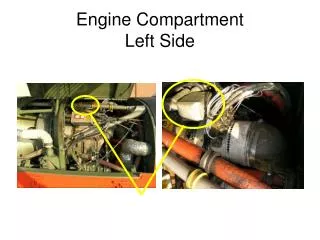
Left Side Discharge Pressure Regulator • Remove Cap to Adjust Valve • Schrader Valve
Adjusting Discharge Pressure Regulating Valve • Unit must be on defrost for adjustment of setting • Proper setting for R404a is ~ 240 to 270 psig • Use 5/16 inch Allen wrench to adjust • CW rotation increases pressure, CCW decreases pressure • Replace cap after adjustment
Right Side Suction Pressure Regulator & Hot Gas Valve • Electrical connection to Solenoid of Valve • Hot Gas Valve • Remove cap to adjust suction pressure regulator valve • Electrical cable to compressor junction box
Adjusting Suction Pressure Regulating Valve • Box temp should be above 5 C • Setting should be ~ 30 to 35 psig for R404A • Use 5/16 inch Allen wrench to adjust • 1 turn changes setting by 2.5 psig • CW rotation increases pressure, CCW decreases pressure • Run system 15 minutes to confirm setting • Be sure to replace cap
Filter Dryer & sight glass with protective coverTo replace Filter Dryer: • Have new filter ready for installation • Perform Low Side Pump down, but make sure to have a slight positive presure • Loosen Bracket • Loosen flare nuts • Replace filter • Tighten flare nuts • Tighten bracket • Open liquid line hand valve
Liquid Line Sight Glass & Filter Dryer • Check for moisture in system • Observe color in sight glass • If yellow replace filter dryer and recycle the refrigerant • Run for 12 hours or until sight glass is green, and look for leaks on the suction side • If not green after 12 hours, replace filter dryer, recycle and look for leaks again
Hot Gas Solenoid Valve for Defrost • Solenoid of the Hot Gas valve • Hot Gas valve • When energized directs hot gas to the evaporator for evaporator coil defrosting • Suction pressure regulating valve
High Pressure Switches • If pressure too high switch opens and de-energizes compressor contactor coil • Right side compressor high pressure safety switch • Unscrew flare fitting to remove switch • Left side compressor high pressure safety switch • Loom removed to show switch wires
Compressor check • With condenser contactor disconnected run unit • Discharge pressure should increase until high pressure switch opens • Close hand valve on receiver • Compressor should pump down to 15 – 20 inches Vacuum or lower • Check current on L1, L2 and L3; 7 to 12 Amps is OK
TXV Placement and Adjustment • TXV located in unit • Proper Bulb location • Tightly clamped to suction line • After it is properly located and clamped, bulb is wrapped with insulation (not shown) • Remember TXV is set at factory and should not need adjustment
Thermal Expansion Valve (TXV) • Sensing Bulb • Capillary line • Power Element • Liquid Line in • Line out to Distributor • Equalizer Line • Removable Cap for adjustment
TVX Adjustment is Seldom Required • Pull container down to -20 C • Remove cap from TX with adjustable wrench • Adjust superheat (SH) setting with refrigeration wrench • CCW reduces SH and CW increases SH • Do not adjust more than 1 turn • Let system run and settle out • It may take as much as 30 minutes for the system to balance after the adjustment • Replace cap
Detecting Blockage in Refrigeration System • Blockage is usually caused by dirt, moisture, or TXV power element loosing its charge • Blockage can be detected by lower than normal suction pressure and reduced capacity • When moisture in the system exceeds the capacity of the dryer to remove it, ice will form in the dryer. This causes a pressure drop and the liquid refrigerant will evaporate. There may be frost on the dryer and/or the liquid line leaving the dryer. • There will not always be frost visible, but the liquid into the dryer should be warm and the liquid out should be cold • Dirt or moisture may cause the TXV to stick in one position • Check this by watching the suction gauge to see if the TXV is modulating. It the suction pressure stays steady the TXV is stuck. The evaporator return air temp must be at -5 C or below to check this. • Check for frozen TXV • Shut unit down • Wait ~ 20 minutes for ice on TXV to melt • At start up unit operation should be normal, after running for awhile if the TXV again sticks and does not modulate, then the problem is moisture. • If after start up, unit operation has not changed it is most likely dirt in the system or the TXV element has lost its charge
Properly Adjusted TXV Conditions • Suction Line from Evaporator • Should be frost on suction line • Possible frost on suction service valve (not shown) • Little or no frost on end of bell • Oil sump should feel warm
Evaporator Coil with Temperature Probes • Hot Gas Defrost Line • Return Air temperature probe • Defrost temperature probe
Condenser Section with Grill removed • Condenser fan • Motor junction box • Coils
Evaporator Supply Air Discharge • Louvers removed to show supply air port • Evaporator fan pulls return air through evaporator coil • And blows it through this opening into the cargo area • Louvers prevent short cycling of supply air back into evaporator section
Liquid Receivers with Sight Glasses Left Side Right Side
Fusible Plug and Purge Valve of Receiver • Purge Valve • Fusible Plug • Hand Valve • Purge Valve from rear • Fusible Plug from rear
Removal of Non-Condensable Gasses • Existence of Non-Condensable Gasses is the major cause of high discharge pressure. • Air and Non-Condensable Gasses collect at the top of receiver • Refrigeration reclaim equipment must be connected to the purge valve on the receiver • Hose from reclaim equipment must be able to depress Schrader valve • Remove small amount of refrigerant through reclaim device • Observe discharge pressure for 5 minutes • Repeat until discharge pressure is normal, saturated discharge pressure should be 11 to 17 degrees C above the ambient • If discharge pressure fails to return to normal, reclaim refrigerant charge, pump system into a vacuum and recharge with refrigerant
Refrigerant Leak Testing • Check all joints and fittings • The preferred method for leak detection is use of an electronic leak detector • Leak testing with soap suds will reveal only larger leaks • Portable electronic leak detectors are usually used for field testing
Mega-Ohm Testing • Purpose: test motor insulation with high Voltage DC • A Go-No-go proof test of motor insulation • Megger will produce voltage pulse and indicate pass or fail • Used to check compressor and fan motors • Three basic types: Hand crank, line operated and battery • Test Voltage: • Device rating up to 100 Vac – test voltage is 100 to 250 Vdc • Device rating 440 to 550 Vac – test voltage is 500 to 1000 Vdc • Device rating 2000 Vac – test voltage 1000 to 2500 Vdc • Caution: Never touch test leads during test and electrically isolate the motor being tested
Test Procedure • Record nameplate information • Select test voltage • To test insulation between lead and earth ground, connect 1 terminal to the lead and the other to a good earth ground • To test between a winding and frame, connect 1 terminal to the lead and 1 terminal to ground • Test L1, L2 and L3 • For hand crank megger, turn at ~ 160 RPM • Megger will indicate pass or fail • Record test results, test every 8 to 12 months