Download
1 / 10
100 likes | 162 Views
The NPDG Motion System for Detector Array Alignment. Christopher B. Crawford University of Tennessee NPDG Collaboration DNP Meeting, Nashville, TN 2006-10-27. Introduction. NPDG probes the Parity Violating (PV) weak hadronic interaction Interference of strong (PC) and weak (PV) vertex

E N D
The NPDG Motion System for Detector Array Alignment Christopher B. Crawford University of Tennessee NPDG Collaboration DNP Meeting, Nashville, TN 2006-10-27
Introduction • NPDG probes the Parity Violating (PV)weak hadronic interaction • Interference of strong (PC) and weak (PV) vertex • Low backgrounds: -5 x 10⁻⁸ expected asymmetry • insensitive to MOST background physics processes (PC) UP-DOWN Asymmetry LEFT-RIGHT Asymmetry Cartesian invariants
Left-Right Asymmetries • Three processes lead to LR-asymmetry • PC npdg asymmetry • Csoto, Gibson, and Payne, PRC 56, 631 (1997) • np->np elastic scattering • beam steered by analyzing power of LH2 • eg. 12C used in p,n polarimetry at higher energies • P-wave contribution vanishes as k3 at low energy • Mott-Schwinger scattering • interaction of neutron spin with Coulomb field of nucleus • electromagnetic spin-orbit interaction • analyzing power: 10-7 at 45 deg 0.23 x 10⁻⁸ 2 x 10⁻⁸ ~ 10-8 at 2 MeV (Michael Gericke et al.)
Motivation • U-D and L-R asymmetry mixing • from misalignment (rotation) of detectors • goal: suppression LR asymmetry by factor of 100-1 = sin(0.57 deg) • Geometry factors • account for extent of target and detector • can be measuredinstead of MC calculation • Detector systematics • demonstrate understanding of rates
detector target geometry factor 3-d position explicit z dependence Formalism • detector yield depends on distance • extract positions from the gradient
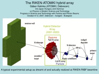
CsI(Tl) Detector Array • 4 rings of 12 detectors • 15 x 15 x 15 cm3 each • VPD’s insensitive to B field • detection efficiency: 84% • current-mode operation • 5 x 10⁷ gammas/pulse • counting statistics limited
Detector Motion Stand • constructed at TRIUMF • < 0.001” position precision • extensive safety features • LabVIEW computer interface
Data and Analysis • yields measured over 5x5 grid in x and y • over-determined for study of linearity • targets: B4C, Cd, LH2 • analysis • detector rates normalized by beam monitors • pedestals and empty target subtracted • Y(dx,dy) fit to obtain absolute detector positions • relative detector positions compared with physical survey of array • need to be corrected for extended geometry by Monte Carlo
Results - Cd target, ring 2 x = 5.6 mm y = 2.8 mm x position (mm) x position (mm)
Conclusions • technique for measuringdetector positions demonstratedwith success on Cd target • 5 mm precision ~ 1 deg. • 50 x suppression of L-R asymmetry • LH2 target measurements in progress • first run affected by venting of target • next run in December