Download
1 / 49
490 likes | 672 Views
Project MegaGrid Building the Oracle Grid Reference Architecture. Akira Hangai Oracle Partner Engineering EMC Corporation. Agenda. Introduction Enterprise Grid Computing Primer Enterprise Grid Computing and Information Lifecycle Management Project MegaGrid Overview

E N D
Project MegaGridBuilding the Oracle Grid Reference Architecture Akira Hangai Oracle Partner Engineering EMC Corporation
Agenda • Introduction • Enterprise Grid Computing Primer • Enterprise Grid Computing and Information Lifecycle Management • Project MegaGrid Overview • Anatomy of Project MegaGrid • Capacity Planning • Infrastructure Design • Deployment • Provisioning • Enterprise Grid Computing and Information Lifecycle Management • Q&A
What Are the Problems IT Face? • Traditional architecture • A series of “islands” • Resources statically assigned to a specific service • A demand for any service… • …Fluctuates over time • …Causingthe changes in the utilization of resources • Consequently… • Hard to react to the fluctuating demands • Hard to utilize resources • Hard to scale Data Center
What Is the Grid Computing Solution? • Standardization • The server equipment • The OS platform • Deployment methods • Management procedures & tools • Consolidation • Network infrastructure • Storage infrastructure • Multiple application services • Shared resources in a single environment for higher utilization
How Does the Grid Computing Approach to Problems? Traditional problems Grid Approaches Heterogeneous resources Standardization Scattered islands Consolidation Components management Virtualization/Automation Fluctuating demands Resource Utilization High cost of deployment and maintenance Lower Total Cost of Ownership
Enterprise Grid ComputingandInformation Lifecycle Management
High Large App A App B Data Value (Solid) Data Amount (Dashed) App C App D Low Small Information Lifecycle Management Time Both the value and amount of data change over time!
Service Consolidation Enterprise Infrastructure Tiered Networked Storage Resource Provisioning End-to-End Connectivity Data Movement Higher Resource Utilization with Lower TCO Grid Computing and Information Lifecycle Management Enterprise Grid Computing Model Grid Infrastructure Model Information Management
Traditional IT Problems High maintenance, lack of scalability, lack of reusability… Industry Leaders Implementing Grid Technologies What Is Project MegaGrid? Collaborating on Enterprise Grid Computing Model Standardization, consolidation, automation, utilization Allied as Project MegaGrid to Develop Best Practices Merging technologies, integration, reducing technical risks Delivering white papers that provide design, deployment and operational methodology recommendations
What Technical Areas Project MegaGrid Address? Grid Approaches Project MegaGrid Standardization Standardizing on existing components and technologies from the partners Consolidation • Developing infrastructure • design guidelines • Deploying multiple applications Virtualization/Automation Developing best practices for managing virtualized resources Resource Utilization Developing dynamic resource provisioning methodologies and guidelines Other Standard Operational Issues • Business Continuity • Backup/Restore • Disaster Recovery
Consolidate partners’ technologies Address each technical area introduced by employing the Grid Computing Model How to design a large environment? How to build and scale? Performance? Management? Utilization? Provisioning? Why Grid? Develop the joint best practices for each technical area using the real-world applications What Is Project MegaGrid Trying to Accomplish? Deliver a series of joint technical white papers Accumulate the deliverables to build a joint reference architecture for the Enterprise Grid Computing deployment
What are the Project MegaGrid Activities? 2004 2005 2006 Q1 Q2 Q3 Q4 Q1 Q2 Q3 Q4 Q1 Q2 Q3 Q4 Phase 1 Phase 2 Phase 3 36nodes 66 nodes 144 nodes Infrastructure Design Infrastructure Scaling-Out Infrastructure Scaling-Out Configuration Guidelines Multiple Applications Deployment Deployment Guidelines Refresh Planning in Progress Deployment Guidelines Performance Monitoring and Resource Provisioning Management Integration RAC Scalability and Performance Disaster Recovery Phase 1 Completed with three white papers published! Phase 2 Completed with another three white papers published! Business Continuity Technology collaboration Best practices development Seamless integration
Telco service-provisioning OLTP application E-Business Suite Real Application Clusters Database Control Business Intelligence Grid Control Ultra Search What Components Are Used in MegaGrid Environment? Red Hat Linux Enterprise Linux 3.0 EMC ControlCenter PowerPath CLARiiON CX 700 Celerra NS700 Dell PowerEdge 1750/1850 MDS 9509 Dell PowerEdge 7250 Symmetrix DMX 1000 Celerra CNS Catalyst 6509
Oracle ASM Disk Group “+EBS” Disk Group “+US” Disk Group “+BI” Disk Group “+OID” Disk Group “+TELCO” Symmetrix DMX1000 CLARiiON CX700 DMX Device Group “IA64” DMX Device Group “IA32” CX Storage Group “IA64” CX Storage Group “IA32” Service Consolidation Clients accessing multiple applications Specific services are assigned with a set of servers. E-Business Suite Ultra Search Business Intelligence Internet Directory Telco OLTP RAC Database “EBS” RAC Database “US” RAC Database “BI” RAC Database “OID” RAC Database “TELCO” A RAC database services each specific application. A site-wide single ASM manages the disk groups for all the RAC databases
Calculate the total bandwidth requirement per node Break down IOPS per node Estimate aggregated IOPS Add the fault tolerance requirements to the size Add the backup requirements to the size Estimate initial data size and growth rate Capacity Planning Flow Primer Services and Servers (CPU) Storage Performance Storage Capacity Determine Business Functions and Service-Level Objectives Create services and define the workload based on the “Service, Module, and Action” model Estimate required capacity Design Develop the storage classes Develop the server classes Design the infrastructure “Capacity Planning” joint white paper contains detailed information
Service and Server CPU Capacity Planning • Determine the business functions and service-level objectives Example • Create services and define the workload based on the “Service, Module, and Action” model • Instrumentation • Execute dbms_application_info.set_module(‘RouteReport’,’DisplayRoute’); • Service Performance Threshold • DBMS_SERVER_ALERT.SET_THRESHOLD() • SERVICE_ELAPSED_TIME, SERVICE_CPU_TIME • Monitoring • Execute dbms_monitor.serv_mod_act_stat_enable(service_name =>’Telco’,module_name =>’’Routereport’,action_name=>’DisplayRoute’);
Storage Capacity Planning Estimate initial data size and growth rate for all the applications (E.g., 500GB initial, double over two years, 1TB total) Add the fault tolerance requirements (E.g., 2TB with RAID1, 1.nTB with RAID5) Add the backup requirements to the size (E.g., Additional 1TB for a full, another 1TB for 5 incremental) Estimate aggregated throughput and IOPS (E.g., 2GB/sec, or 300,000 IOPS) Calculate the total bandwidth requirement per node (E.g., 2GB/sec for 16 nodes = 128MB/node/sec or 300,000/16 = 18,750 IOPS/node) Choose the appropriate storage class and build the configuration (E.g., 1,200 IOP per spindle, 16-way striped = 19,200 IOPS per LUN)
Payroll Inventory Report Business Intelligence Ultra Search Application Services Application Grid Application Servers JDBC, SQLNet RAC RAC RAC RAC Database Instances Database Grid Database Servers ASM Provisioning FC-SW DG Automatic Storage Management (ASM) Disk Group Disk Group Recovery Group DG DG Storage Grid Device Group Device Group Device Group NAS Group EMC ControlCenter Navisphere DG SAN Provisioning Networked Storage RAID1+0 RAID5 ATA NAS MegaGrid Service Architecture Concept
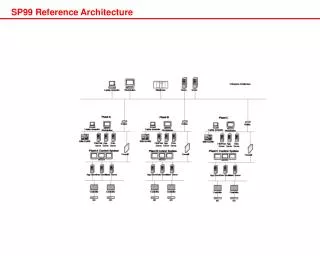
NAS NN WAN LAN IP Network Public/App-DB Private Interconnect NAS/iSCSI Management Server Farm a001 a002 a003 aNNN b001 b002 b003 bNNN Storage Farm SAN Fabric 1 SAN Fabric 2 Server and storage farms horizontally scalable (“scaling-out”) Server and storage farms horizontally scalable (“scaling-out”) Storage 01 Storage 02 Storage NN MegaGrid Infrastructure Concept
Management VLAN (1GigE) Public VLAN (1GigE) NAS VLAN (1GigE) Interconnect VLAN (1GigE) Fabric 1 (2Gbps) Fabric 2 (2Gbps) MegaGrid Topological Architecture IP Cisco Catalyst 6509 Each switch uplinks to 2 x aggregation switches via 10Gb Dell PowerEdge 7250 EMC PowerPath Dell PowerEdge 1750/1850 EMC PowerPath SAN Cisco/EMC MDS 9509 224 ports Cisco/EMC MDS 9509 224 ports 8 IP ports, 4 per switch 32 ports, 16 per switch 8 ports, 4 per switch 20 ports, 10 per switch Symmetrix DMX 1000 CLARiiON CX 700 Celerra CNS Celerra NS700
Infrastructure Design Summary • Scalability Design • Multiple services = Multiple server nodes • Multi-tiered = sizable inter-server communication • Clustering = multiple nodes accessing the same storage • Capacity Planning • Application workloads • Scale-out • Design Concerns • Port density: bandwidth requirements between server nodes: ISL or big switches? • High availability: LACP, EMC PowerPath
Storage Configuration • 16-way Metavolume • (RAID1+0) • Granular “building-block” model • Volume Logix (Symmetrix) and Storage Group (CLARiiON) technology for provisioning • Compliant with the existing “best practices” for performance • Complementary to the Oracle ASM model • DMX 1000-P • 32 FA ports • 144 disks • 32 GB cache • 16-way BCV Metavolume • (RAID0) • 4+1 RAID5 Groups on FC drives • CX 700 • 8 front ports • 30 FC drives • 15 ATA drives • 4+1 RAID3 Groups on ATA drives • NS 700 • 12 GigE ports (2 x 6-port SP) • 15 FC disks • 4+1 RAID5 Groups
HBA IF IF Storage Provisioning Primer (2) “Port-to-port” ACL “Port-to-port” ACL (3) “Service” ACL; i.e., LUN-to-WWN ACL (most granular) Server WWN-based zoning Access control allowing communication between certain WWNs Port-based zoning Access control allowing communication between certain ports SAN switch IF IF IF IF IF IF IF IF Device Masking Access control allowing communication from certain WWNs to certain LUNs SAN Storage IF IF IF IF IF IF IF IF Front-end adapters LUN Masking Creation of logical volumes and assignment of volumes to specific interfaces within the storage system Cache Backend adapters LUN LUN LUN LUN LUN LUN LUN LUN LUN LUN LUN LUN LUN LUN LUN LUN (1) “Export” ACL
Server Node Class 2-001 Server Node Class 1-001 HBA HBA P1 P1 P2 P2 0 0 0 0 1 1 1 1 Director 3/SPA B A B A Director 14/SPB 0001 0009 0011 02A1 02B1 02C1 0019 0021 0029 02D1 02E1 02F1 MegaGrid Storage Provisioning Model: SAN • LUN Masking Configuration on the DMX • (One-time only) • Assign consistent device IDs per Director port to all the devices. 2) Zoning Configuration on the SAN Switches (One-time only) Create a zone per HBA (initiator) port (e.g., P1@1-001) with all the available DMX Director ports (e.g., 3A0, 3B1, 14A1, 14B0) on the same switch. Note that in this model, zoning alone will not allow access to the devices; it merely allows the communication between two points. SAN Switch (Fabric 1) SAN Switch (Fabric 2) 3) Device Masking on the DMX (Storage Group on the CX) (On-demand – dynamic provisioning) Allow access from a specific WWN (HBA port, or initiator) to certain devices by adding the entry to the Volume Logix database on the DMX or Storage Group configuration on the CX DMX or CX Dev Group A Dev Group B
Server Node Class 1-001 Server Node Class 2-001 NIC NIC eth2 eth2 eth3 eth3 cge0 cge0 cge1 cge1 cge2 cge2 cge3 cge3 MegaGrid Storage Provisioning Model: NAS • Export Configuration on the NS • (One-time only) • Export certain NAS file systems through a certain Data Mover to a specific subnet (security implication). Use FS Group to combine file systems for ease of management for SnapSure. IP Switch (NAS VLAN) 2) Mount on Server Nodes (On-demand – dynamic provisioning) Simply mount on server nodes using the “mount” command. To make it “permanent,” add the entry to the /etc/fstab file. LACP Data Mover 02 Data Mover 03 Celerra NS700 FS Group /nas01 /nas02 NAS provisioning is the standard NFS procedure. /nas03 /nas04
Storage Configuration and Provisioning Summary • Granular building-block configuration • Manageable provisioning technology: Device Masking • Volume Logix • Storage Group • High Availability • PowerPath for multi-pathing I/O • Standard technologies such as LACP
Oracle E-Business Suite Oracle Database 10g Telco OLTP Oracle Internet Directory Oracle Cluster Ready Service +OID +US Recovery Area +EBS +TELCO +BI MegaGrid Deployment and Provisioning Model Installable Software Packages Installed on… Shared Storage (applications) Mounted on… Server Farm Sharing… Shared Storage (data) • Application software is installed on shared storage to avoid duplicate installation. • The software is mounted on a server when it’s dynamically allocated to run the service. • The server then accesses the data for that service on the shared storage.
Configuration Management Server Farm NAS ASM Read executables and init.ora file from the NAS device 1 1 2 3 4 • Shared NAS Devices • Executables • Password files • init<SID>.ora files (pfiles) • System logs (trace) Oracle ASM on Shared SAN Devices Disk Group “+EBS” Return the SP file location on the ASM disk group 2 Disk Group “+TELCO” Contact the ASM instance 3 Disk Group “+OID” Return the config-uration 4 Initialization parameters are stored on the ASM disk group. Configuration for other apps are stored on the shared NAS devices. Run the services
Software Deployment and Configuration Summary • Utilize NAS to install binaries once • Naming conventions for consistency
Oracle Database 10g RAC Scalability • Completed in Phase 1, announced at Oracle OpenWorld San Francisco 2004. • A separate RAC database was deployed on each server-class cluster. • PE1750 and PE7250 clusters were tested during Project MegaGrid Phase 1, using Dell/Intel servers with EMC platforms. • SMP cluster was tested on a Unix platform with FC-AL storage.
Oracle Database Performance Monitoring • Monitoring Business Transactions • Externalized in V$SQL and V$SQLAREA • Set with • OCIAttrSet, • setEndToEndMetrics • DBMS_APPLICATION_INFO • HINT: There is no direct way to correlate a SQL statement with a service. Specify the module name in such a way that the service can be identified. • Database Alerts • Thresholds can be defined with the DBMS_SERVER_ALERT PL/SQL package • The most important service levels are • CPU time per call • Response time per call “Performance Management” joint white paper published
Oracle Database 10g Monitoring using AWR • AWR (Automated Workload Repository) • “Statspack built into the kernel” • Metrics and statistics are collected in a database repository • Repository is stored in the SYSAUX database • Snapshots are automatically collected every hour for the whole cluster • Across the cluster each snapshot has the same snapshot id. • Guidelines • If you want to keep the snapshots for more than seven days add more space to the SYSAUX tablespace • If more database instances are added to database add more space to the SYSAUX tablespace • After every installation and every update of one of the components collect a new baseline. New baselines can be collected with the CREATE_BASELINE procedure.
Storage Performance Monitoring • Symmetrix DMX • EMC ControlCenter Performance Manager • Throughput, service time, busy stats, and capacity utilization per physical device granularity • Trending information • EMC Solutions Enabler • Simple command-line based tools for throughput and busy stats • Scriptable • CLARiiON CX • EMC Navisphere Management Suite • Throughput, service time, busy stats, and capacity utilization • Trending information • NaviCLI • Simple command-line based tools for throughput and busy stats • Scriptable • Celerra NS/CNS • Celerra Manager • Web-based tool for throughput, service time, busy stats, and capacity utilization per file system and device level “Performance Management” joint white paper published, available on http://www.emc.com/megagrid/
The Foundation of Resource Provisioning: Infrastructure • End-to-end Connectivity • All the servers can communicate with each other with no bottleneck (i.e., ISL). • All the servers can see all the storage devices, both SAN and NAS, so any combination of the servers can assume running any application service. • Key Technologies • Enterprise-level storage systems (able to support a large number of clients) • Enterprise-level networking, both for IP and SAN (avoiding obvious physical limitation of ISL bottleneck) • Advanced provisioning technology: Volume Logix (Symmetrix) and Storage Group (CLARiiON) to simplify storage provisioning
Enabler of Resource Provisioning: Application • End-to-end Monitoring • Mapping of the runtime environment, from the highest-level application down to the storage. • All the data have to be statically stored on some specific storage; they have to be identified easily with storage management mechanism. • Key Technologies • Instrument application • DBMS_APPLICATION_INFO.Set_Module() • Set alerts • DBMS_SERVER_ALERT.Set_Threshold() • Define Resource Manager Plans • DBMS_RESOURCE_MANAGER • Enable more fine grained statistics collection • DBMS_MONITOR
For More Information… • White Papers Available Since Q4 2004 • Capacity Planning • Deployment Best Practics • Performance Monitoring for Large Clusters • White Papers Newly Available • Infrastructure Design • Resource Provisioning • Storage-based Data migration • All are available from • http://www.dell.com/megagrid • http://www.emc.com/megagrid • http://www.intel.com/go/megagrid • http://www.oracle.com/megagrid