Download
1 / 35
350 likes | 437 Views
Detuning of T18 after high power test. Jiaru Shi 18.04.2012. Outline. RF measurement of CERN-Build T18 Comparison before and after high power test Detuning Analysis Old results (From Juwen Wang and Toshiyasu Higo) Related simulation Geometry Change and analysis. CERN built T18.

E N D
Detuning of T18 after high power test Jiaru Shi 18.04.2012
Outline • RF measurement of CERN-Build T18 • Comparison before and after high power test • Detuning Analysis • Old results • (From Juwen Wang and Toshiyasu Higo) • Related simulation • Geometry Change and analysis
CERN built T18 RF measurement Before high power test after high power test
Before high power test After high power test Increased standing wave Regular cells are fine
Analysis using the code for tuning from bead-pull data • See detuning of input matching cell • The detuning of last two cells are calculated from the standing wave patter, or the reflection from the output matching. Details next slides. (Note: while tuning, these two cells are tuned to correct the standing wave).
Standing wave patternReflection (both phase and amplitude) • The imaginary part of this reflection can come from detuning of the last regular cell cell(N-1). Decrease of frequency • Or the matching cell: Cell(N) Increase of frequency: • Important note: the phase advance between the last two cells is ~100deg. Not 120 deg! • Note: imag part of reflection comes from detuning, while real part of reflection comes from unmatched coupling before last regular cell (N-1) before Matching cell (N)
Amplitude Measurement of T18-SLAC #1 Before and After High Power Test Juwen Wang @ SLAC 11421.7 MHz at 21.32°C, N2 Before high Power test 1350 hours 11421.87 MHz at 20.4°C, N2 After high power test
Phase Measurement of T18-SLAC #1 Before and After High Power Test Juwen Wang @ SLAC 11421.87 MHz at 20.4°C, N2 After high power test 11421.7 MHz at 21.32°C, N2 ore high Power test
Amplitude Measurement of TD18-SLAC Before and After High Power Test Juwen Wang @ SLAC 11424.5 MHz at 21.46°C, N2 Before high Power test 11424.56 MHz at 21.1°C, N2 After high power test
Phase Measurement of TD18-SLAC Before and After High Power Test Juwen Wang @ SLAC 11424.56 MHz at 21.1°C, N2 After high power test 11424.5 MHz at 21.46°C, N2 ore high Power test 16.5° Select bead pulling frequencies based on the same measurement condition for both before and after high power test
Amplitude Measurement of T18-SLAC #1 Before and After High Power Test Juwen Wang @ SLAC T24 11424.1 MHz at 20.02°C, N2 Before high Power test 11424.15 MHz at 20.4°C, N2 After high power test
Phase Measurement of T24-SLAC Before and After 800 Hours High Power Test Juwen Wang @ SLAC 11424.1 MHz at 21.2°C, N2 Before high power test 11424.1 MHz at 21.1°C, N2 After high Power test 6º Select bead pulling frequencies based on the measurement condition to get 2π/3 phase advance for both before and after high power test
Similar Standing-Wave pattern for T(D)18 T18-SLAC T18-CERN T24-SLAC TD18-SLAC
Summary of the detuning Note: T(D)18 structures have similar design where the phase advance between last two cells is ~100 deg. Making it hard to tell at Nth or at N-1th cell. It seems at the last cell.
RF measurement before/after baking • T24 12G N1 • Same configration • Temperature df calculated
Phase S21 • Delta f ~10kHz
T24 12G N2, leak fix at mode launcher • With and without wire, no direct comparison • Phase compare N/A because change of RF flange adapter • df < 50kHz, Reflection increase 100k grid
CERN PSI N2 after baking, df<100kHz • (same situation)
TD18 post-HPT @CERN • TD18 post-HPT (High Power Test) analysis • 1. Chamfer From: Markus Aicheler
TD18 Chamfer100 um -1MHz Chamfer TD18 Fill the 100um Chamfer +1MHz
Electromagnetic field • Scaled to 150 MV/m Eacc • P = (-epsilon0 E^2 + mu0 H^2)/4 • static simulation • Material: Copper E = 110GPa • Max deform: 0.06um, very small. • 0.06um 12kHz • not the right direction • HFSS result: Iris deform 10um ~ 2MHz Circular Wg E field pull B field push Matching cell
Asymmetry heating? Circular Wg Surface heating expansion? Matching cell
The source of detuning is not clear, but we find that. The MHz detuning corresponds to a geometry change that can be measured! • The structure is cut open and critical dimensions are measured
T18 CERN N2 Cut • 1: measure the profile of tuning bump, compare with the tuning history Tuning bump visible by eye
Height of tuning bump v.s. recorded tuning • Good agreement “< +/- 1MHz”
T18 CERN N2 Cut • 2: measure the distance between irises.
Distance between irises (gap) Half-B Half-A Error +-3 um. Three points are measured: “left” and “right” close to the cell wall, “center” close to the iris region Last cell is longer in “center”.
Simulation with deformed output matching iris in HFSS • Single cell simulation gives 3MHz detuning from ~15 um “iris deform”. • Full structure simulation shows similar standing wave pattern.
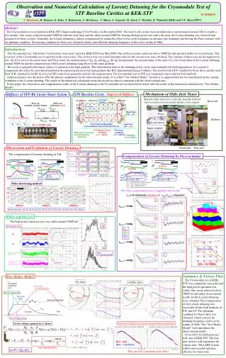
Summary (1) • It’s a critical issue for the reliability and the lifetime of the accelerating structures. • Almost every structure has an increased reflection from output, causing a standing wave pattern. For the same type of structure, the patterns are very similar. • Geometry measurement on the T18 (CERN N2) shows deformation on the output matching iris This explains the increased reflection. (Most probably, this is also the case for the other 3 structures) • In CLIC nominal design with compact coupler from the side, there will be no iris with such field asymmetry. • Input side, cut into halves? Or take it iris by iris. Measure the profile of the whole input matching iris • multiple-physics-coupled simulation: the deform of matching iris and the asymmetrical pulsed heating.
Summary (2) • Frequency change of regular cells is observed in several structures, in TD18, but not in T18s; in T24s. in TD24? • To be analyzed in near future: TD24 taken out from TBTS. • RF measurement, Cut, and dimensional control.