Download
1 / 37
370 likes | 514 Views
Next Generation Interconnection Technology for High-Performance Computer Systems. Jason D. Bakos Department of Computer Science University of Pittsburgh. Talk Outline. Brief introduction to system interconnection technology Examples Challenges Electrical and optoelectronic signaling

E N D
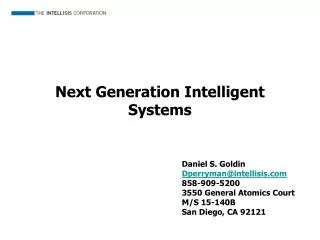
Next Generation Interconnection Technology for High-Performance Computer Systems Jason D. Bakos Department of Computer Science University of Pittsburgh
Talk Outline • Brief introduction to system interconnection technology • Examples • Challenges • Electrical and optoelectronic signaling • High-performance interconnection technology research at Pitt • Optoelectronic Multi-Chip Modules (OE-MCM) • Multi-Bit Differential Signaling (MBDS) • Dissertation research • Lightweight Hierarchical Error Control Codes (LHECC)
System Interconnect • Network-on-chip • Multi-Chip Modules • System-level interconnect • Short-haul • High-performance • Printed circuit boards • Backplanes • Peripherals
Packaged chip Packaged chip Source: Intel Corporation Challenges for System Interconnect • Signal integrity • Capacitance/inductance • Noise • Timing/jitter • Area • I/O pads precious • Driver size
Electrical Signaling • Single-ended • 1 wire per bit • Disadvantages • Requires shared reference • Susceptible to noise • Switching noise • Differential (LVDS) • 2 wires per bit • Data encoded as {01} or {10} • Advantages • Large GDP • EM coupled transmission lines • Low switching noise • Low noise => low voltage swing • Disadvantages • Wasteful in I/O pads
Top-emitting laser area pads Incoming laser GaAs die area pads GaAs die Optoelectronic Signaling • Optical signaling • Used in long-haul signaling • Chip-level optical signaling • Dense high-speed channel arrays • Orthogonal to die • OE conversion • Vertical Cavity Surface Emitting Lasers (VCSEL) • Gallium-Arsenide (GaAs) • “direct-bandgap” • High-speed photodetectors • GaAs • Issues: • Packaging • Manufacturability driver circuitry receiver circuitry photodetector array VCSEL array flip-chip bonds
mirror microlens photodetector VCSEL Si die Si die PCB waveguide photodetector VCSEL Si die Si die PCB Optoelectronic Architectures • “Free Space” • “Guided Wave”
Talk Outline • Brief introduction to system interconnection technology • Examples • Challenges • Electrical and optoelectronic signaling • High-performance interconnection technology research at Pitt • Optoelectronic Multi-Chip Modules (OE-MCM) • Multi-Bit Differential Signaling (MBDS) • Dissertation research • Lightweight Hierarchical Error Control Codes (LHECC)
OE Conversion Technology Area pads Window VCSEL site Passive alignment mark
OE Interconnect using Fiber Image Guides Dense lattice of fiber cores 5-20 um diameter, 2K-15K cores/mm2 Side Bottom Top
OE-MCM Demonstrator IN Chip 3 OUT Chip 1 Chip 2 Chip 1 Chip 2 Chip 3
Multi-Bit Differential Signaling (MBDS) • Differential (LVDS) channel • Multi-Bit Differential (MBDS) channel • Current-mode drivers • Data encoded as • {01} or {10} • Advantages • Low switching noise • Large GDP • Coupled transmission lines • Low noise => low voltage swing • Disadvantages • Two connections for each bit • Wasteful in I/O pads • Data encoded with fixed number of ones • “N-choose-M (nCm)” symbols • {0011}, {0101}, {0110}, {1001}, {1010}, {1100} • Advantages • Same noise rejection as differential • Higher information capacity
“N choose M (nCm)” Encoding Effective bits Code set size • EXAMPLE • 6-wire MBDS channel • code size = 20 codes • effective bits = 4 • equivalent to 8-wire differential channel • 25% fewer pads (8 versus 6) • 25% less power (4 1-bits on versus 3)
MBDS Test Chip • Test setup • .5 um SiGe chip implementing • 2, 4, 6, 8-wide MBDS drivers and receivers • Test board with 8” channels • MBDS -> MBDS receivers • MBDS -> commercial LVDS receivers • Tested at 700 Mb/s
Talk Outline • Brief introduction to system interconnection technology • Examples • Challenges • Electrical and optoelectronic signaling • High-performance interconnection technology research at Pitt • Optoelectronic Multi-Chip Modules (OE-MCM) • Multi-Bit Differential Signaling (MBDS) • Dissertation research • Lightweight Hierarchical Error Control Codes (LHECC)
Error Correction Codes • Error correction codes used to increase signal integrity • Noisy communication channels • Ex: wired/wireless signaling, storage mediums • Examples: • Cellular networks, deep-space signaling, digital TV/HDTV transmission, hard/optical disks • ECC codes require information overhead • Acceptable for very noisy channels • Minimize by applying code over large blocks of data • Examples: • 11 bytes for hard disks, 187 bytes for HDTV
ECC Introduction • ECC encoding over large blocks requires • Memory • Computation • Encoding/decoding performed using software or dedicated ASICs • Decoding performed at low speeds (megabits at most) • Traditional ECC techniques not practical for off-chip interfaces • Memory, real estate • Need new class of ECC code for system interconnect • Encode/decode with small space • Small block size • Low overhead • Possible with MBDS signaling?
1011 1101 0111 1110 0011 0001 1000 0010 0100 1 error 3 errors 0011 1111 1001 2 errors 1010 0101 0110 0000 nCm Encoding: Inherent Error Detection • Most types of bit errors can be detected at receiver Odd-number of bit errors Even-number of bit errors
4c2 symbol set => binary value 0011 00 0101 01 0110 10 1001 11 1010 ? 1100 ? 6 cw 6 cw 36 combinations 5 bits 4c2 4c2 2 bits 2 bits nCm Encoding: Unused Code Space • Each nCm code set has unmapped code words • Use this to offset overhead required for error control • Use multiple MBDS channels in parallel Req’d number of channels for extra bit • Do not use nCm symbols that are counteractive to ECC
Need for Error Control Coding 6 bits • Single or multiple bit errors in nCm symbols invalidates entire corresponding binary message • Some types of errors fool receivers • Need error control code that: • Works over nCm-encoded channels • Uses properties of nCm channel code to minimize overhead • Solution: • Encode data over parallel MBDS channels • Establish rules governing nCm symbols selected to encode data 00110011 00111011 ????
Hierarchical Encoding Use nCm symbolsto build code set which conforms to binary distance for ECC start with raw binary data Raw binary data Encode portion of data, set rules for nCm symbol selection high-level code Symbolic ECC block Encode remainder of data using nCm symbols Code word over parallel MBDS channels low-level code
1100 0101 0011 0110 1001 1010 Low-Level Code • nCm code sets have distance=2 • t = floor((d-1)/2) • Set new distance by partitioning into equal-size subsets • Maximize number of symbols/subset • Subsets: • 0 => {0011, 1100} • 1 => {0101, 1010} • 2 => {0110, 1001} • If subset is known, bit errors may be corrected • Example: 0111, subset=2 • Correct to 0110 Example: 4c2, distance=4
Can correct: • erasures • errors k data symbols n-k parity symbols block size=n High-Level Code: Linear Block Codes • Checksum • Requires 1 parity symbol • Can correct 1 erasure • Near-MDS code • Corrects erasures: • Number of parity symbols - 1 • Corrects errors: • (Number of parity symbols – 1) / 2 • Restrictions: • Symbol base must be prime or power of a prime • If symbol base = pm, max block size = pm+1 - 1 • MDS code (Reed-Solomon) • Can correct erasures: • Number of parity symbols • Can correct errors: • Number of parity symbols / 2 • Restrictions: • Symbol base must be prime or power of a prime • Max block size = symbol base + 1
b bits (c-data) (s-data) 01010010010010010100 0101001001 0010010100 base conv. 2->s Parity symbols base conv. 2->c Data as nCm symbols Parity as nCm symbols Data symbols Encoding LHECC
Encode 111101… 1112 = 213 2 1 • Compute checksum parity… 2 1 0 • Encode 101… 1 0 1 bit grp. 2 1 0 Example #1: Encoding • Assume 3 x 4c2 channels • Low level • s=3, c=2 • High level • (3,2) checksum code • s-data • sk = 9 cw (3 bits) • c-data • cn = 8 cw (3 bits) • code rate = 6 bits / 12 wires • “Free” ECC 1001 0101 1100
grp. 2 1 0 ? 1 0 cw 1001 0101 1100 1101 0101 1100 Example #1: Decoding • Decoder: • If invalid code word is detected • Determine subset • Use minimum distance decoder • Assume bit error occurs… • X + 1 = 0 (mod 3), X = 2 • Symbol in error must be 0110 or 1001 • dist(1101,0110) = 3, dist(1101,1001) = 1 • Corrected symbol is 1001
MBDS driver MBDS receiver MBDS driver encoder MBDS receiver binary decoder binary MBDS driver MBDS receiver LHECC Advantages • LHECC codes provide correction and additional detection to MBDS links • LHECC codes are lightweight: • Parity symbols in high-level only consume portion of nCm symbol data • Requires less parity symbols in high-level code (vs. traditional codes) • Takes advantage of inherent properties of nCm channel code • LHECC encoders/decoders require only a few hundred logic gates • Pipelined and operate at core speed
encoded code words (CMOS digital) encoded code words out (100K load) Input is sampled at midpoint Driver input cwn-1 cwn cwn+1 Outputs sampled at t(input) + latency Receiver output cwn-1 cwn cwn+1 latency Link Modeling • Replicated for each channel in the link • Consistent sequence of random code words transmitted
Error Source Modeling • Goal: Capture link behavior in the presence of modeled error sources • Determine relative error results for links with and without LHECC support • Error sources from link model: • Jitter • Transmission line attenuation, crosstalk • Noise from transistors Input to receiver 1.8 GCW/s 2.2 GCW/s 2.6 GCW/s 3.0 GCW/s 3.4 GCW/s 3.8 GCW/s 4.2 GCW/s 4.6 GCW/s Receiver output
Supply Noise • Add independent Vdd noise to driver and receiver • Intel: measured supply noise on a busy 1.5 V Pentium 4 processor • 17-20 mV standard deviation • To generate: • Assume links operating at core switching frequency • Generate white Gaussian noise • Sampled at 20 GHz for 20 us • Apply passband butter filter to noise, 200 MHz band centered on op. frequency stdev=.275 stdev=.0388
Fringe Capacitance in Driver • Assume layout parasitics and packaging add capacitance effects in driver current-steering legs • Where it hurts drivers most • Adds additional crosstalk
Conclusions • System-level interconnect • Next-generation interconnect • optoelectronic (high density channel arrays) • serialized electrical using encoding techniques • LHECC over MBDS channels offers lightweight error control • Increases signal integrity, reliability, noise immunity, and maximum transmission rate • Utilizes small encoders and decoders