Download
1 / 46
1.04k likes | 1.87k Views
Proper duct design and fan selection are important to avoid unnecessary inefficiencies, unacceptable indoor air quality and noise levels, and discomfort of the occupants. Chapter 12: Fans and Building Air Distribution.

E N D
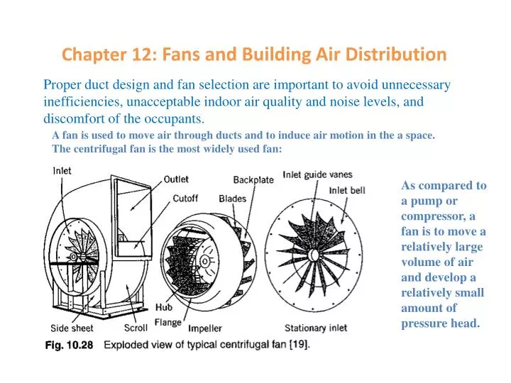
Proper duct design and fan selection are important to avoid unnecessary inefficiencies, unacceptable indoor air quality and noise levels, and discomfort of the occupants. Chapter 12: Fans and Building Air Distribution A fan is used to move air through ducts and to induce air motion in the a space. The centrifugal fan is the most widely used fan: As compared to a pump or compressor, a fan is to move a relatively large volume of air and develop a relatively small amount of pressure head.
Images of centrifugal fans https://www.google.com/
Images of axial fans https://www.google.com/
Energy transferred from the fan to the air between the inlet and outlet of the fan. Each term has the unit of length, referred to as head (the power in the equations is negative based on the sign convention) Fan Relations The total pressure or stagnation pressure is the static pressure plus dynamic pressure. Elevation effect in a fan is normally negligible, a significant difference from a pump.
Fan Relations wg: Inch of water gauge. 1 wg = 249 Pascals at 0oC = 0.00249 bar = 0.0361 psi (lbf/in2)
Fan Relations The pressure here is actually pressure head developed by the fan.
Fan Noise Backward-curved fan blades are generally considered to have a lower noise.
The required capacity (cfm) and system total pressure head at the design point. • A good combination of efficiency, costs, acoustics, and physical size. • The danger of the fan operating in the unstable (surge) region at low flow rate (partial capacity) unless care is taken in selection and fan speed is controlled. Fan Selection- backward-curved blade fan The backward-curved blade fan should always be operated to the right of the point of maximum pressure for surge consideration. See Fig. 12-4: power input to the fan is still relatively high when flow rate approaches zero.
The performance is plotted on a logarithmic scale. In this case, a system characteristic (S-S) is a straight line. • Used for low, medium, and high pressure head HVAC systems. Highest efficiency designs of all centrifugal fans. For a given duty, operate at the highest speed. • The performance curve is stable. The fan has a load-limiting horse power characteristic. Near free delivery (zero pressure rise), horse power is lower, and there is no danger of overloading the motor. Fan Selection- backward-curved blade fan
Used in low pressure head HVAC applications, such as furnace, central station units, and packaged air-conditioning equipment. • Tends to have the lowest efficiency and operate at the lowest speed of the various centrifugal fans. • Should be applied well to the right of the peak pressure point. • The horse power rises continuously toward free delivery, and this must be taken into account when fan is applied and the motor is selected. Fan Selection- forward-curved blade fan
If a fan is to be connected to a duct system through an elbow, the complex velocity profile at the outlet should be developed into a relatively uniform profile through a sufficiently long straight duct between the fan outlet and the elbow. Otherwise, significant loss may occur (particularly due to the high peak velocity at the outlet. Fan outlet/inlet conditions
Fan outlet conditions The lost coefficient may be found using Table 12-5.
The lost coefficient is also affected by the blast area and by the position of the elbow. Fan outlet conditions
The percentage of the effective length is the ratio of the duct length to the one effective duct length as shown in Table 12.2. Fan outlet conditions
If it is necessary to install an elbow at the inlet of the fan, additional loss may occur which may be calculated by using Eqs. (12-7) and (12-8), but with different lost coefficients. Fan inlet conditions Transition from rectangle to round shape needed for cases d&e.
Use of pressure may be desirable Air Flow in Ducts Pressure loss
Velocity Pressure Lost head due to friction in a straight (Major Loss in Fluid Mechanics), constant area duct may be presented in special charts
A common practice to take into account the roughness effect is to use a correction factor that is applied to the pressure loss obtained for a galvanized metal duct (for smooth galvanized metal duct, f = 0.02, defined as e = 0.0005 ft). Duct roughness effect
Circular diameter equivalents of rectangular ducts for equal friction and capacity
In contrast to fluid mechanics, the local losses here are called dynamic losses (not called minor losses) because of its greater magnitude) Air flow in fittings
r is the radius of the curved turn of the vane, and L is the extended length of the vane after the curved turn Air flow in fittings
Transitions-Round to Round In this case, the section 0 is the outlet of the transition. A larger angle represents a short transition distance
Air flow in fittings The loss coefficients associated with the branch and main sections are based, respectively, on the velocity pressures of the branch and main sections.
When the branch flow rate is much smaller than the main, the flow from the branch is entrained by the flow through the main, which increases the total pressure of the branch and balances pressure loss through the branch. So that the loss coefficient may be negative. On the other hand, if the flow rate through the branch is much higher than the main, the flow through the main is entrained by the flow through the branch and the total pressure through the main is increased, resulting in a negative loss coefficient.
Because of the 90 degree angle, the entrainment effect of the small straight flow by the large branch flow is diminished.
It is often convenient to express the effect of fittings in terms of equivalent length of a straight duct Equivalent lengths of Fittings C may be found from the loss coefficient tables of fittings, f may be approximately found from Table 12-13.
12 in. (30 cm) 15 ft. (4.6 m)
To deliver a specified amount of air to each diffuser in the conditioned space at a specified total pressure. • To ensure a reasonably quiet system. • A low noise level is achieved by limiting the air velocity, by using sound-absorbing duct materials or liner, and by avoiding drastic restrictions in the duct such as nearly closed dampers. • Generally have a pressure loss from about 0.08 in. wg per 100 ft (0.65 Pa/m) to about 0.6 in. wg per 100 ft (5 Pa/m), depending on the system capacity. • Small commercial systems will operate in the lower end of the pressure range with maximum velocities less than 1200 ft/min (6m/s). • The duct system should be nearly free of leaks when the ducts are outside the conditioned space. Duct Design
Duct Design https://www.google.com/
The loss in total pressure selected for the design of a duct system is an important consideration to reduce fan power. Large commercial and industrial duct systems are usually designed using velocity (for noise concern) or pressure loss as a limiting criterion. Duct Design- An Example
The equal friction method may be used for all types of systems including small light commercial as well as large VAV systems. • The balance capacity method is particularly good for constant flow systems where air flow rate to each space is critical. • The static regain method is useful for large constant flow method. Duct Design – Sizing
The principle of the equal friction method is to make the pressure loss per foot of duct length the same for the entire system. A desired feature of this method is the gradual reduction of air velocity from fan to outlet, reducing the noise problem. • The usual procedure is to assume the velocity in the main duct adjacent to the fan in accordance with the design criteria. The known flow rate of a longest run then establishes the duct size and the lost pressure per unit length. This same pressure loss per unit length is then used throughout the other runs of the system. After sizing the system, the designer must compute the total pressure loss for each run. Iterations may be needed if the pressure loss in any run exceeds the maximum value permissible. This can be done by adjusting the velocity assumed and repeating the calculation procedure. A lower velocity would reduce the pressure loss but it would increase the duct size, which increases the first cost of duct system. A tradeoff may be needed between these conflicting factors. • If the layout is symmetrical with all runs from fan to diffuser approximately the same length, this method will produce a good balanced design. If the layout is not symmetrical, the short runs will have to be dampered to maintain a desired flow rate to each space. This, however, may not represent a problem because dampers are needed for VAV systems anyway. Equal-Friction Method
Example 12-11 b a
The total pressure losses from the fan to outlets are automatically balanced as all the outlets would have the same space pressure. The basic principle of the method of design is to make the loss in total pressure equal for all duct runs from fan to outlet under required air flow rates. • The design procedure is the same as the equal friction method for the determination of the pressure loss of the longest run. The procedure then switches to the sizing of the remaining runs in terms of the same pressure loss. • The method is particularly good for constant flow systems where maintaining the air flow rate to each space is critical, or when the installation of dampers in the ducts is difficult. Balanced-Capacity Method