Download
1 / 83
830 likes | 996 Views
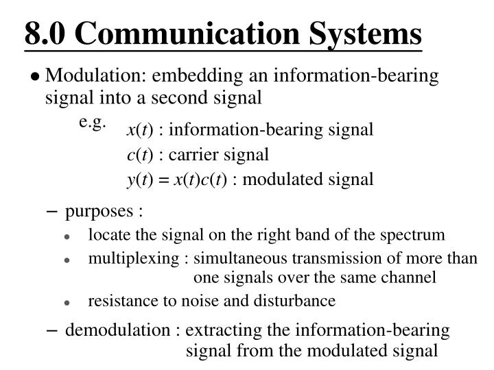
8.0 Communication Systems. Modulation: embedding an information-bearing signal into a second signal e.g. x ( t ) : information-bearing signal c ( t ) : carrier signal y ( t ) = x ( t ) c ( t ) : modulated signal. purposes : locate the signal on the right band of the spectrum

E N D
8.0 Communication Systems • Modulation: embedding an information-bearing signal into a second signal • e.g. • x(t) : information-bearing signal • c(t) : carrier signal • y(t) = x(t)c(t) : modulated signal • purposes : • locate the signal on the right band of the spectrum • multiplexing : simultaneous transmission of more than • one signals over the same channel • resistance to noise and disturbance • demodulation : extracting the information-bearing • signal from the modulated signal
8.1 Amplitude Modulation (AM) and Frequency-Division Multiplexing (FDM) Complex Exponential Carrier • Modulation • information-bearing signal • Demodulation • See Fig. 8.1, p.584 of text
Sinusoidal Carrier • Modulation • See Fig. 8.4, p.586 of text
Sinusoidal Carrier • Demodulation • Synchronous demodulation (detection) • See Fig. 8.6, 8.8, p.588, 589 of text • A lowpass filter gives x(t)
Sinusoidal Carrier • Demodulation • Synchronous demodulation (detection) • If the demodulating carrier is not in phase with the carrier • output signal reduced by • synchronization required. • phase-locked loops.
Sinusoidal Carrier • Demodulation • Asynchronous demodulation (envelope detection) • envelope (the smooth curve connecting the peaks) carries the information, can be extracted in some other ways • always positive • See Fig. 8.10, 8.11, p.591, 592 of text • the carrier component consumes energy but carries no information • See Fig. 8.14, p.593 of text
Sinusoidal Carrier • Double-sideband (DSB)/Single-sideband (SSB) • double-sideband modulation uses twice the bandwidth • DSB/WC (with carrier) , DSB/SC (suppressed carrier), upper-sideband, lower-sideband • See Figs. 8.19, 8.20, 8.21, 8.22, p.598-601 of text • a 90°phase-shift network can be used
Frequency-Division Multiplexing (FDM) • each signal allocated with a frequency slot. Many signals transmitted simultaneously over a single wideband channel using a single set of transmission facilities • See Figs. 8.15, 8.16, 8.17, p.594-596 of text • See Fig. 4.27, p.326 of text • Signals mixed in time domain but separated in frequency domain.
Frequency Division Multiplexing (p.62 of 4.0)
8.2 Pulse Modulation and • Time-Division Multiplexing • Amplitude Modulation with a pulse train carrier • See Figs. 8.23, 8.24, p.602, 603 of text • A lowpass filter gives x(t) if sampling theorem is satisfied, ωc > 2 ωM
Amplitude Modulation with a pulse train carrier • This remains true as long as c(t) is periodic, represented by a sequence ak. Sinusoidal AM is a special case here. Impulse train sampling is the case ∆ → 0. • Pulse-Amplitude Modulation • pulse amplitudes corresponds to the sample values • example : rectangular pulses (sample-and-hold) • See Fig. 8.26, p.606 of text • Sampling theorem applies.
Time-Division Multiplexing (TDM) • Each signal allocated with a time slot in a period T. • Many signals transmitted simultaneously over a single channel using a single set of facilities • See Figs. 8.25, 8.27, p.605, 606 of text • Signals mixed in frequency domain but separated in time domain.
Intersymbol interference • pulses distorted during transmission and causing interference to adjacent symbols • See Figs. 8.28, 607 of text • Pulses with zero intersymbol interference • (1) • See Figs. 8.30, 609 of text
Intersymbol Interference • x[1] • x[2] • x[3] • It is the sample values rather than pulse shapes to be transmitted • Distortionless transmission via distorted channels • intersymbol interference
Intersymbol interference • (2) • Pulses with zero intersymbol interference • P1(jw) with odd symmetry about • See Figs. 8.31, 610 of text
Pulse coded modulation (PCM) • binary representation of pulse amplitude (sample values) and binary transmission of signals • much more easier to distinguish between 1’s and 0’s
8.3 Angle/Frequency Modulation Angle Modulation • phase modulation (PM) • frequency modulation (FM) • phase modulation with x(t) corresponds to frequency modulation with dx(t)/dt