Download
1 / 23
230 likes | 380 Views
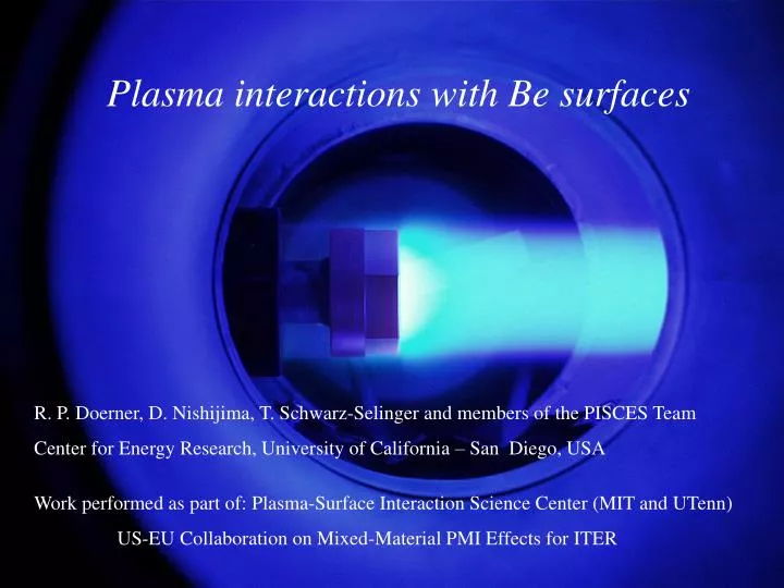
Plasma interactions with Be surfaces R . P. Doerner , D. Nishijima , T. Schwarz- Selinger and members of the PISCES Team Center for Energy Research, University of California – San Diego, USA Work performed as part of : Plasma-Surface Interaction Science Center (MIT and UTenn )

E N D
Plasma interactions with Be surfaces R. P. Doerner, D. Nishijima, T. Schwarz-Selinger and members of the PISCES Team Center for Energy Research, University of California – San Diego, USA Work performed as part of:Plasma-Surface Interaction Science Center (MIT and UTenn) US-EU Collaboration on Mixed-Material PMI Effects for ITER
The PISCES-B divertor plasma simulator is used to investigate ITER mixed materials PSI. • PISCES-B is contained within an isolated safety enclosure to prevent the release of Be dust.
PISCES-B has been modified to allow exposure of samples to Be seeded plasma PISCES P-B experiments simulate Be erosion from ITER wall, subsequent sol transport and interaction with W baffles or C dump plates, as well as investigation of codeposited materials using witness plates
Outline of Presentation PISCES • Erosion in the plasma environment • Comparison to TRIM and ion beam data • Surface characterization • Role of morphology • Redeposition/sticking efficiency • Summary
PISCES Be erosion yield measurements in PISCES • Two techniques are used to measure physical sputtering yield • Weight loss measurements, use low density plasma to reduce redeposition (i.e. long ionization mean free path). • Line emission spectroscopy, uses high density plasma to minimize geometrical loss terms (i.e. short ionization mean free path). • These presentation will focus on the weight loss technique and changes to spectroscopic measurements that are normalized to weight loss measurements. [He plasma on Be, weight loss are 5-10 times lower than TRIM calculations, He plasma on C, weight loss agree with TRIM calculations].
Significant variations in the Be sputtering yield are measured PISCES discrepancy between - JET - PISCES-B - ion beam – TRIM - sputter yields (< 45%) (< 0.7%) (< 8%) (< 3.5%) J. Roth et al., FED 37(1997)465. Incident ion energy ~100 eV
PISCES Uncertainties in sputtering yield measurements Uncertainties in weight loss measurements: • Surface contamination • Incident ion energy • Ion flux measurement • Ion species mix (molecular ions) • Redeposition fraction • Surface morphology changes • Atomic D adsorption on the surface (secondary ion yield) Uncertainties in absolute spectroscopic measurements: • Atomic physics database • Electron energy distribution (non-Maxwellian) • Angular distribution of sputtered particles • Geometrical loss fraction
Native beryllium oxide surface is removed early during the plasma exposure PISCES • Distinctive oxygen lines near 777 nm can monitor erosion of O from surface • Background helium plasma does not change (second order He I line) • Larger ion energy will remove oxide layer quicker • BeO (0,0) molecular band emission (@ 470.86 nm) is not detectable
AES reveals a relatively ‘clean’ Be surface after sputtering yield measurements PISCES
PISCES Incident ion energy is corrected for plasma potential. Ion flux is uniform over sample surface. Ion flux calculated from upstream Langmuir probe agrees with total current collected on the sample manipulator when biased into Isat (with ~10%) PISCES-A space potential measurements show Vpl ~ 1-2 Te Eion = |Vbias | - 1.5Te Target From D. Whyte et al, NF 41 (2001) 47. From B. LaBombard et al, JNM 162-164 (1989) 314.
PISCES Molecular ion fractions are calculated from zero-d rate balanced model, based on measurements • Model uses the atomic and molecular processes to the right • Rate equations predict molecular ion fractions based on ne, Te, B, NH2 • Turbulent radial transport is assumed (1/B scaling) • Model is verified with molecular ion species measurements From E. Hollmann et al., Phys. Plasmas 9 (2002) 4330.
PISCES Molecular ion effects change both the shape and magnitude of sputtering yield curve Shape of measured yield agrees with molecular ion model predictions. Magnitude is a factor of ~5 too low.
PISCES ERO calculates 10-20% ionization of sputtered Be in the PISCES-B plasma • Shape of Be I (457 nm) axial profile agrees well with experimental profiles • Magnitude of profiles are normalized • Molecular ion fractions provided by previous model • No Be deposition observed on W or C targets exposed to D plasma (no wall source) From D. Borodin et al, Phys. Scr. T128 (2007) 127.
Surface morphology evolution with time / fluence Be surface before plasma exposure after PISCES mass loss: spectroscopy: morphology change can account for a factor of 2 in reduction of the yield
1keV, H2+ 7.3E21 ions/cm2 Similar yield evolution with time/fluence is documented in the literature Mattox and Sharp, J. Nucl. Mater. 1979: PISCES morphology change can account for a factor of 2 reduction of the yield
Plasma atoms remaining in the near surface also can reduce the sputtering yield by a factor of 2-3 PISCES From C. Björkas “maximum” – static TRIM + MD “minimum” – SDTrimSP with 50% of D (reasonable limit)
Gross erosion is expected to remain constant with increasing Be redeposition/influx PISCES • N = G * (1-R), where N = net erosion, G = gross erosion, R = redeposited fraction • In PISCES-B, Gross = net erosion with no Be seeding (λion is large compared to rplasma, so redeposition is small) • Ion influx from Be oven is identical to sputtered atoms that are ionized in the plasma and redeposited on the target, this allow a controlled and independent variation of the Be influx to the target
Erosion/deposition balance in Be seeded high flux D discharges PISCES Mass loss • Use Be oven seeding to balance surface erosion to test input parameters of material migration models • Mass loss measures net erosion • Spectroscopy measures gross erosion (Be I line) • Y Be→Be ≈ Y D→Be, and low concentration of Be • When incident/seeded Be ion flux = sputtered flux of Be, net erosion should = 0. ion fluence: 1022/cm2 target temperature < 320K
No change in mass loss is measured when Be seeding flux equals sputtering of Be by D PISCES Mass loss • ADAS database is used • Be flux from Be II (313.1 nm) and background plasma flow velocity (E. Hollman JNM, PSI-19) • Be ion flux is verified during no bias discharges, when weight gain is measured (net deposition) • Net erosion stays constant, implying gross erosion must increase • Erosion yield of 0.15% can only be compensated by seeding 2.8% Be 2.8% ion fluence: 1022/cm2 D/Be plasma target temperature < 320K
Beryllium seeded He discharges target: bias: < -40V results in E ≈ 30eV He ion flux: 5·1018 cm-2s-1 Be seeding: nBe/nD = 0 – 4 % PISCES target oven sputter yield He on Be @ 30eV: Y = 0.15 % (measured) Gross erosion : During ‘no Be seeding’ discharge, Gross ≈ Net erosion
Different behavior is observed experimentally PISCES • Net erosion stays constant until influx >> sputtering rate • Gross erosion increases with increasing Be influx to target • Reduced sticking of depositing Be, or increased re-erosion could explain observations • Similar reduced sticking needed to model CD4 and WF6 injection experiments in TEXTOR (from A. Kirschner) • Possibly similar to C-MOD modeling difficulties reported by J. Brooks (PSI19)
What PMI issues are still unresolved PISCES • Sputtering Yield – we believe we can explain the observed, low sputtering yields in PISCES-B, due to surface morphology and fuel atoms within the target surface (no Be seeding) • How many gas atoms are in the surface during exposure? • Gross/Net Erosion – drastic differences in behavior of gross erosion during Be seeding indicates the simple theory regarding the benefits of prompt redeposition may need to be revisited • 10 times more influx is needed to balance erosion and force net erosion to zero • Low sticking probability or high re-erosion possible explanations
Be seeding fraction (i.e. influx) is at most in the percent range, so Be self-sputtering and Be reflection can be neglected