Download
1 / 42
590 likes | 1.37k Views
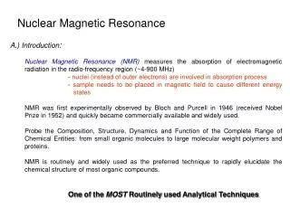
Nuclear Magnetic Resonance. Absorption of electromagnetic radiation from 4 MHz to 900 MHz Nuclear process Radiation absorbed by nuclei Sample must be placed in strong magnetic field Used for determining structure Two types of NMR Continuous wave Pulsed wave

E N D
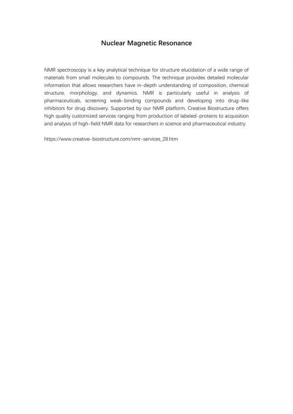
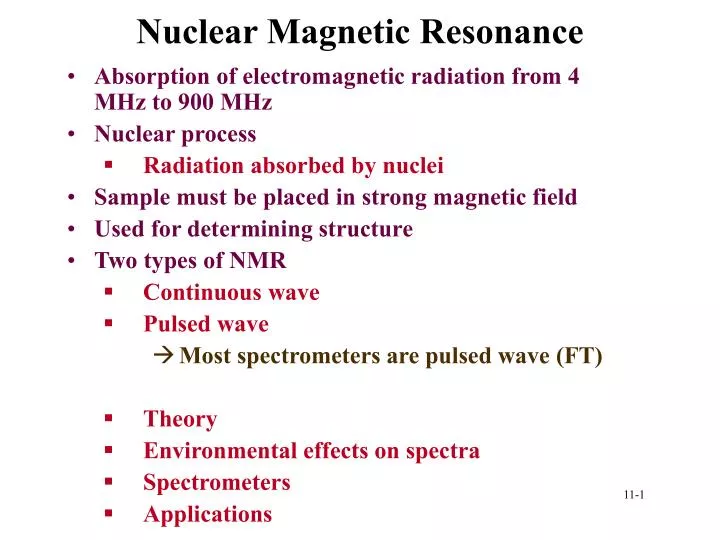
Nuclear Magnetic Resonance • Absorption of electromagnetic radiation from 4 MHz to 900 MHz • Nuclear process • Radiation absorbed by nuclei • Sample must be placed in strong magnetic field • Used for determining structure • Two types of NMR • Continuous wave • Pulsed wave • Most spectrometers are pulsed wave (FT) • Theory • Environmental effects on spectra • Spectrometers • Applications
Theory • Quantum description • Spin • Nuclei with spin have angular momentum (p) • p is integral or half integral multiple of h/2p • For a given p, maximum spin values is I • Spin quantum number • Nuclei has 2I+1 states • m=I, I-1, ….., -I • States energies differ in magnetic field • For proton • p=1/2 • m= ½, -1/2
Energy levels • Magnetic moment becomes orientated in two directions • ½ is lower E, -1/2 is higher • + or -
Distribution • What is distribution between states • Based on Boltzmann’s equation • For proton in 4.69 T field at 20 °C
Theory • Magnetic moment related to magnetogyric ratio (g) • m=gp
Procession in a magnetic field • Angular velocity (radians/s) • w=gB • Larmor frequency
Relaxation Process • Non-radiative relaxation processes (thermodynamics!). • If the relaxation rate is fast, then saturation is reduced • If the relaxation rate is too fast, line-broadening in the resultant NMR spectrum is observed • Two major relaxation processes; • Spin - lattice (longitudinal) relaxation • T1 relaxation time • Spin - spin (transverse) relaxation
Spin Lattice Relaxation • Nuclei in the lattice are in vibrational and rotational motion, which creates a complex magnetic field • magnetic field caused by motion of nuclei within the lattice is called the lattice field • lattice field has many components • Some components will be equal in frequency and phase to the Larmor frequency of the nuclei of interest • These components of the lattice field can interact with nuclei in the higher energy state • cause them to lose energy (returning to the lower state) • energy that a nucleus loses increases the amount of vibration and rotation within the lattice (resulting in a tiny rise in the temperature of the sample). • relaxation time, T1 (the average lifetime of nuclei in the higher energy state) is dependant on the magnetogyric ratio of the nucleus and the mobility of the lattice • As mobility increases, the vibrational and rotational frequencies increase, making it more likely for a component of the lattice field to be able to interact with excited nuclei • at extremely high mobilities, the probability of a component of the lattice field being able to interact with excited nuclei decreases.
Spin-Spin Relaxation • Spin - spin relaxation describes the interaction between neighboring nuclei with identical precessional frequencies • differing magnetic quantum states • nuclei can exchange quantum states • a nucleus in the lower energy level will be excited • the excited nucleus relaxes to the lower energy state • no net change in the populations of the energy states • the average lifetime of a nucleus in the excited state will decrease • can result in line-broadening • T2
Chemical Shift • A molecule may contain multiple protons that exist in unique electronic environments. • Therefore not all protons are shielded to the same extent. • Resonance differences in protons are very small (ppm). • Measure differences in resonance energy relative to a reference. • Tetramethylsilane (CH3)4Si (TMS) provides highly shielded reference (set to 0ppm). • Nuclear Shielding • Nuclei are shielded by electrons. • Induced field associated with orbiting electrons. • Require stronger magnetic field than H0. • Increased shielding requires greater applied field strength to achieve resonance.
NMR Spectra • Hypothetical NMR spectra. • Shows TMS reference. • Chemical shifts (d, ppm) given relative to TMS
Chemically Equivalent • Protons in the same environment will have the same chemical shift. • Protons in different environments have different chemical shifts. • Protons with the same chemical shift are referred to as chemically equivalent. • Integrated area of peak is proportional to the number of protons.
Sample Spectra • The first spectra is that of a symmetric molecule, all protons are equivalent. • Second spectra is that of a molecule containing two types of protons. • Correlation chart for proton chemical shift
Nuclear Shielding/Deshielding • Valence electron density can shield nucleus from applied field. • Electronegative substituents can draw elecron density away. • Results in deshielding. • Anisotropy: p-electrons and induced magnetic field. • Results in shielding and deshielding zones.
Spin-spin Splitting and n+1 Rule • Each type of proton “senses” protons on adjacent carbon atoms. • Spin state of nearby protons contributes to the proton evironment and apparent magnetic field. • General rule is that the signal is split into n+1 peaks. n = number of equivalent neighboring protons. • Spacing between component peaks referred to as coupling constant (J). • J coupling is representative of the degree to which protons interact. • J usually 0-18Hz
1,1,2-trichloroethane • NMR spectrum for 1,1,2-trichloroethane • Hb proton signal split into doublet • Ha proton signal split into triplet • J couplings are the same for Ha and Hb signals • Ha integral is 1/2 that of Hb
Magnetic Equivalence vs. Chemical Equivalence • NMR differentiates between nuclei based on environment. • In constrained systems, two protons on the same C-atom can be in different environments. • These protons can demonstrate spin-spin splitting.
Higher Field Strengths • At higher field strengths differences in energy between spin states is increases. • Improved signal resolution. • Coupling constants are independent of field strength.
Carbon-13 NMR • ~1.08% of C atoms are the 13C isotope. • Do not usually see C-C spin-spin interactions. • Can see coupling between C and attached H’s. • Magnetic moment m of 13C is low. • Resonances of 13C nuclei are ~6000 fold weaker than 1H resonances. • Therefore most useful information is chemical shift. • Covers a range of 0-200ppm. Ethyl phenylacetate
Proton Decoupled • Proton coupling can provide information about number of protons. • Often useful to decouple protons. • Irradiate sample with broad spectrum of frequencies. • Substituents on C can enhance of reduce signal. • Protons enhance the 13C signal.
Spectrometer • Magnet • Shim and lock • Sample probe • Coils and receiver
NMR imaging with a trivalent lanthanide tracer has been applied to the study of transport and sorption in ion exchange resins The tracer, Gd3+, is a highly effective NMR contrast agent and an excellent chemical analog for trivalent actinides Trivalent lanthanide 7 electrons in f orbital Results from these studies can be used to improve modeling and prediction NMR imaging
NMR Imaging • Advantages: • 2 and 3-D analysis of heterogeneous granular structure • Inherently non-invasive probe of spatial structure • Near real-time analysis of static and dynamic processes • Flexibility to adapt experimental methods to various sample types and configurations • Limitations: • Paramagnetic and/or ferromagnetic impurities can create artifacts and image distortions • Low porosity can lead to long experiment times (proton NMR)
Ion-Specific Exchange Resins • Developed to partition similar inorganic species from waste streams • Cooperation with French partners in CNAM, ENSCP • Synthetic organic structures with phenolic functional groups • Resorcinol formaldehyde (RF) resins were used in these experiments (11.5 meq/g dry) • RF resins were crushed, sieved (80-200 ASTN mesh), washed, and conditioned to Na+ form
Nold De-aerator stepper motor w/ hydraulic piston for pressure control vacuum pump NMR Flow Systemshowing evacuation, de-aeration, and over- pressurization systems
NMR Basics - spin relaxation • T1 Relaxation: spin-lattice or longitudinal relaxation of the spin system measured using an inversion recovery sequence where, Mz(t) = Mo[ 1 - 2 (exp(-t /T1)) ] Inversion Recovery Curve -T1 Determination DI Water vs. 0.1 mM Gd Solution 1 T1 for 0.1mM Gd in Sand is 400ms 0.8 0.6 o 0.4 Relative Magnetization-Mz(t) 0.2 0 0.05 0.25 0.40 0.60 0.75 0.80 0.95 1.00 1.15 1.35 0.00 0.10 0.15 0.20 0.30 0.35 0.45 0.50 0.55 0.65 0.70 0.85 0.90 1.05 1.10 1.20 1.25 1.30 1.40 -0.2 -0.4 T1for DI Water in Sand is 1730ms -0.6 DI Water -0.8 0.1 mM Gd Solution -1 Time (sec)
T1 Weighting Experiment - Inversion Recovery 5mm tube of H2O surrounded by 0.1mM Gd solution in sand Water signal suppressed Gd Signal Intensity Weighted
sand/resin interface Gd Sorption with Phenolic Resin and Sand8mm diameter by 15mm long sample saturated w/ 1.0 mM Gd
NMR Imaging Studies of 2-D Flow1.0 mM Gd into homogenized RF resin and sand sample Flow direction 1.25cm cm 0.8 Image 1: water saturated sample Image 2: 55ml of 1.0mM Gd in Image 3: 80ml of Gd in Image 4: 110ml of Gd in Image 5: 160ml of Gd in Image 6: 200ml of Gd in Fingering Flow Phenomenon
Resin Column data 1.0 0.9 0.8 End of Gd Flow 0.7 0.6 [Gd]out / [Gd]in 0.5 0.4 #6 0.3 #3 0.2 #5 0.1 #4 0.0 0 100 200 300 400 500 600 700 800 900 1000 -0.1 Total Volume Into Column (ml)
Cool Spots Showing Voids and Low Sorption Sites Hot Spots Showing Gd Sorption Sites Gadolinium Complexation with Phenolic RF Resin8mm diameter by 15mm long resin sample saturated with 1.0 mM Gd solution