Download
1 / 85
850 likes | 1.08k Views
Figure 1.1 Illustration of the modeling of a device (a CD amplifier) with an electric circuit model. Figure 1.2 Illustration of Coulomb’s law and the attraction/repulsion of charges. Figure 1.3 Illustration of the work required to move a charge along a path.

E N D
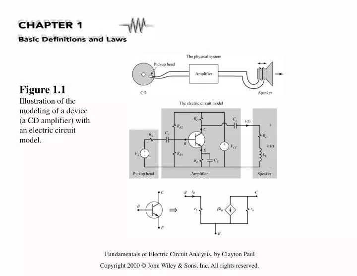
Figure 1.1Illustration of the modeling of a device (a CD amplifier) with an electric circuit model.
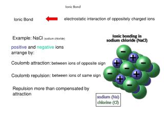
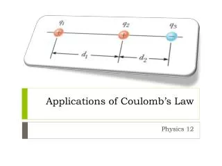
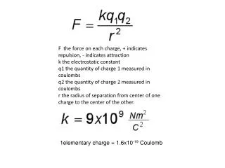
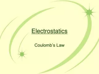
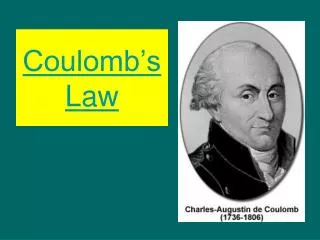
Figure 1.2Illustration of Coulomb’s law and the attraction/repulsion of charges.
Figure 1.3Illustration of the work required to move a charge along a path.
Figure 1.4The similarly of gravitational potential to electric potential.
Figure 1.7 Illustration of (a) current as the rate of movement of electric charge, and (b) the magnetic field associated with that charge movement.
Figure 1.8Illustration of the time history of (a) movement of net positive charge past a point, and (b) the resulting current.
Figure 1.9A lumped circuit element and its associated voltage and current.
Figure 1.10Charging a discharged automobile battery to illustrate the concept of power delivered to or absorbed by an element and the passive sign convention.
Figure 1.11 Illustration of the power delivered to (absorbed by) an element and the power delivered by the element.
Figure 1.12 Examples of the computation of power delivered to or by an element.
Figure 1.13Illustration of an electric circuit as a particular interconnection of circuit elements.
Figure 1.20 Illustration of the concepts of (a) voltage rise and (b) voltage drop.
Figure 1.21 Illustration of a method for correctly writing KVL with reference to the circuit of Fig. 1.19.
Figure 1.22 Another example illustrating a method for correctly writing KVL.
Figure 1.24The seven loops in the circuit of Fig. 1.23, with KVL written for each.
Figure 1.25A useful variant of the method for writing KVL when only one voltage in the loop is unknown.
Figure 1.26Another illustration of writing KVL for a loop where only one voltage is unknown.
Figure 1.27Illustration that KVL is a result of the law of conservation of energy.
Figure 1.32Illustration of(a) the series connection of elements, and (b) the parallel connection of elements.
Figure 1.33Examples to illustrate to proper classification of series and parallel connections.
Figure 1.34Illustration of the concept of equivalent circuits.