Download
1 / 38
420 likes | 658 Views
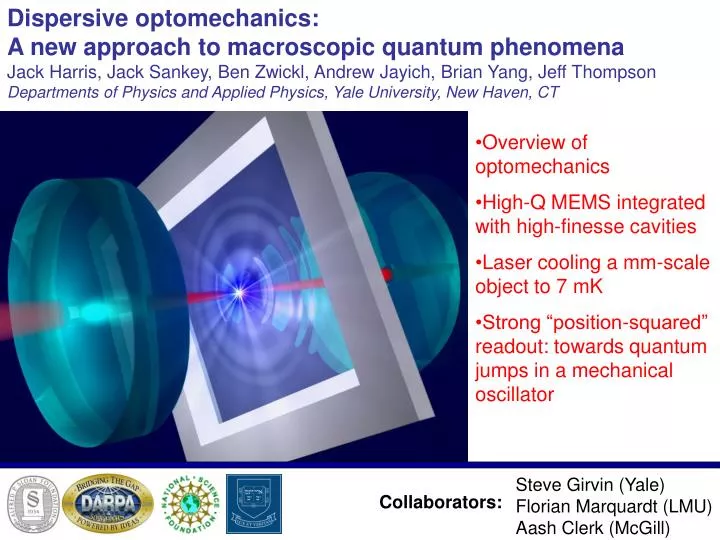
Dispersive optomechanics: A new approach to macroscopic quantum phenomena Jack Harris, Jack Sankey, Ben Zwickl, Andrew Jayich, Brian Yang, Jeff Thompson Departments of Physics and Applied Physics, Yale University, New Haven, CT. Overview of optomechanics

E N D
Dispersive optomechanics: A new approach to macroscopic quantum phenomena Jack Harris, Jack Sankey, Ben Zwickl, Andrew Jayich, Brian Yang, Jeff Thompson Departments of Physics and Applied Physics, Yale University, New Haven, CT • Overview of optomechanics • High-Q MEMS integrated with high-finesse cavities • Laser cooling a mm-scale object to 7 mK • Strong “position-squared” readout: towards quantum jumps in a mechanical oscillator Steve Girvin (Yale) Florian Marquardt (LMU) Aash Clerk (McGill) Collaborators:
Quantum optomechanical systems, c. 1920 drawn by Niels Bohr “Which path” / “Welcher Weg” drawn by J.M. Raimond drawn by Niels Bohr • Does interference disappear? • Measure which path photon takes via recoil (i.e., quantum radiation pressure) Is this possible? What other issues can be addressed?
Mechanical detectors coupled to EM resonators (circa 2008): UCSB, Leiden ENS Yale ENS Cornell NIST LIGO Vienna kg g mg mg ng pg Mass Caltech, Munich MIT ENS JILA IBM Nanotubes, BECs, Atoms, Ions… Oregon
Mechanical detectors coupled to EM resonators: • These devices span: • 1017 in Mass • 109 in Frequency • 1011 in Length • All probe the same physics, all are described by the same Hamiltonian* • Many within 102±1 of quantum limited displacement detection Goals: Classical optical control of mechanical devices* New type of quantum optics / mesoscopics Quantum-limited force & displacement measurements Generation of nonclassical light (squeezed, entnagled) Quantization of macroscopic objects* *Stay tuned
Unified description of optomechanical systems Fixed mirror “spring” x Braginski, JETP (1967) Pin Mechanical mode “Movable” mirror Optical mode Optical mode Mechanical mode Note: Radiation Force = For detuningx:
Unified description of optomechanical systems Fixed mirror “spring” x Pin Mechanical mode “Movable” mirror Optical mode 1) Cavity detuning is proportional to x (so no quantum jumps) 2) A single element confines light, responds mechanically Experimentally difficult!! • What are the possible quantum effects in this system? • Radiation pressure shot noise (quantum back-action) • Ground state of mechanical oscillator • Quantum jumps of mechanical oscillator • What does it take to see these?
Quantum optomechanics: Why is radiation pressure shot noise hard to see? Radiation pressure shot noise: Thermal Langevin noise force: Versus Ratio of quantum to thermal fluctuations One possible figure of merit: • Combine state-of-the-art mirrors with state-of-the-art MEMS • (Finesse = 1,000,000) (Force sensitivity ~ 1 aN/Hz½ ) The main technical barrier to the quantum regime of optomechanics: IBM (Rugar et al) Combine into a single device 1 cm Supermirror
Integrating good mirrors into good cantilevers… • High finesse mirrors: • Amorphous SiO2/Ta2O5 layers - • Strained, mechanically lossy • Good figure / flatness - • Very stiff substrate • At least 2 mm thick, 20 mm dia. - • Sets minimum k, m. • Uncontaminated surface • High quality MEMS oscillators: • Low mechanical loss • Low spring constant • Low mass • Substantial processing • (ion etching, ion milling, lithography, etc.) Is there another approach? Which doesn’t require optical and mechanical functionality in one device?
A new approach: dispersive optomechanical coupling support “spring” x dielectric slab • Practical: Segregates optical and mechanical functionality • Fundamental: Detuning, interaction Hamiltonian qualitatively different Fixed mirror Fixed mirror Pin Optical mode cavity detuning slab position x “Dispersive” coupling similar to off-resonant atom in a cavity
What does detuning actually look like? x rc rc = 0.000 Cavity’s longitudinal resonances
What does detuning actually look like? x rc rc = 0.300 rc = 0.000
What does detuning actually look like? x rc rc = 0.600 rc = 0.300 rc = 0.000
What does detuning actually look like? x rc rc = 0.880 rc = 0.600 rc = 0.300 rc = 0.000
“Big” fixed mirrors provide high finesse • Mechanical device doesn’t need to be very reflective x Nearly full optomechanical coupling even for low-reflectivity cantilever!! rc rc = 0.995 rc = 0.880 rc = 0.600 rc = 0.300 rc = 0.000
The actual device: schematic x rc Invar spacer Ultrastable laser (l = 1,064 nm) & Input optics 50 nm x 1 mm x 1 mm membrane (Norcada, Inc.) • 10-6 Torr (ion pump) • Vibration isolation • T = 300 K
The actual device: membrane 1 mm 1 mm • 50 nm thick SiN: • ~l/8 @ 1064 nm • rc = 0.35 • 1 mm square: • cavity mode diameter is 180 mm, so no diffraction loss • $20 each • Crucial questions: • Optical properties (scatter / absorption)? • Mechanical properties?
Optical characterization: cavity spectroscopy 2.24 Transmission (a.u.) Laser detuning (GHz) 1.12 0.00 532 1064 Membrane position (nm) Fitting gives membrane reflectivity = 0.35 Consistent with 50 nm membrane with n = 2.2 Transmission resonances still look narrow…
Cavity finesse vs. membrane position High loss - antinode empty cavity finesse =175,000 160,000 Data Fit (n = 2.15 + 0.00016 i ) 120,000 Finesse Low loss at nodes of cavity mode 80,000 40,000 0 0 532 1064 1596 Membrane position (nm) Calulcated finesse assuming better end mirrors… empty cavity finesse = 1,000,000 300,000 100,000 500,000 400,000 Theory: finesse > 500,000 seems possible! 300,000 Finesse 200,000 100,000 0 0 266 532 798 Membrane position (nm)
Mechanical ringdown to measure Q T = 300 K n0 = 134,000 Hz Q = 1,120,000 1 (depends on strain in membrane) Amplitude (a.u.) • Q is 2 – 3 orders of magnitude greater than comparably sized devices • 7 aN/Hz½ force sensitivity 0 0 2 4 6 8 10 Time (s) 1 Within an order of magnitude of world-record! T = 300 mK n0 = 119,000 Hz Q = 11,300,000 Amplitude (a.u.) Seems possible to couple state-of-the-art cavities to state-of-the-art MEMS… using only commercial devices! 0 0 40 80 120 160 Time (s)
What can we do with this device? Operating in “linear detuning” regime, dispersive coupling mimics other geometries: But with easier fabrication (high finesse, Q, etc.) Transmission (a.u.) For example, laser cooling…
Laser cooling the membrane (first results): • Monitor membrane’s undriven motion • Extract temperature from either or • Two methods of extracting Teff agree (almost) Pin=100 nW Q ~ 105 Cavity finesse = 16,000 10-22 192 K 42 K Increasing laser power 10-24 28 K Amplitude of membrane motion [m2/Hz] 10-26 1.5 K Pin = 60 μW Q ~ 100 0.5 K 10-28 0.3 K 10-30 116,000 117,000 118,000 119,000 Frequency [Hz] • decrease in ω0 due to negative “optical spring” • decrease in T due to “optical damping”
Laser cooling the membrane (improved setup): (curves are not offset) 10-26 Teff = 2.34 K ± 0.13 K 10-27 Sx(n) (m2/Hz) Teff = 253 mK ± 4.7 mK 10-28 Teff = 80 mK ± 1.8 mK optimizing detuning 10-29 Teff = 13.3 mK ± 0.51 mK 10-30 Teff = 6.82 mK ± 0.61 mK 10-31 126 128 130 132 134 n (kHz) • Theory predicts that same device should cool from T = 300 mK to Teff = 1 mK << • Quantum ground state of a mm-scale object!
What else can we do with this device? 2 Laser frequency (fsr) 1 532 1064 Membrane displacement (nm) Quadratic detuning: Linear detuning: • Phonon number is constant of motion • Cavity has a “shift-per-phonon” Phonon number is not constant of motion • Quadratic coupling g2 diverges as rc ~ 1 Fundamentally different! Cavity only measures (displacement)2
Membrane quantum jumps? In practice, one must measure cavity shift w/ SNR > 1 during membrane phonon lifetime Cavity shift per phonon is: Shot-noise-limited PSD is: Thermal lifetime of n-phonon Fock state is: Membrane temperature (can be laser-cooled!) Bath temperature
Membrane quantum jumps: proposed experiment • Assumptions: • Membrane is laser-cooled to ground state • Cooling laser is then switched off • Watch for transition • Also include: • Corrections to RWA & QND approx’s • Parameters • T = 300 mK • = 532 nm Q = 12,000,000 x0 = 0.5 pm • m = 5 x 10-11 g • wm = 2p x 100 kHz • Pin = 10 mW • F = 300,000 • rc = 0.999 • SNR = 1.0 ?!?!?
Avoided crossings of higher-order cavity modes 4.48 TEM0,0 modes 3.36 Laser detuning (GHz) 2.24 Transmission (a.u.) 1.12 0.00 0 532 1064 1596 membrane displacement (nm)
Avoided crossings of higher-order cavity modes Crossings made possible by “dispersive” geometry. Avoidedness controlled by…? “tweak” the input coupling… 4.48 ~32 kHz/nm2 TEM2,0 triplet 44.8 TEM0,0 singlet 3.36 Laser detuning (MHz) Laser detuning (GHz) 2.24 0.00 ~1.8 MHz/nm2 reff = 0.98 1.12 42.5 85.0 0.00 membrane displacement (nm) 0.00 0 532 1064 1596 membrane displacement (nm)
Avoided crossings depend on membrane tilt: 88 66 44 22 0 44 22 0 Detuning (MHz) Detuning (MHz) 0 17 30 0 15 Membrane displacement (nm) Membrane displacement (nm)
Modelling the cavity eigenmodes: Cavity eigenmodes given by Helmholtz equation: Solve using 4-mode degenerate perturbation theory: Unpertubed eigenmodes Perturbation
Modelling the cavity eigenmodes: Unpertubed eigenmodes (paraxial approximation): longitudinal mode guoy phase wavefront curvature hermite-gauss transverse mode Beam width: Guoy phase: Wavefront radius of curvature: Calculate overlap integrals over membrane volume: -Analytically using approximate eigenmodes -Numerically using exact eigenmodes Main fitting parameters are: -Coarse displacement of membrane from cavity waist -Tilt of membrane relative to cavity axis
Results of perturbation theory calculation: • Ignoring mode coupling gives sinusoidal detuning trivially • Including coupling lifts degeneracies, makes crossings avoided: tilt = 0.5 mrad offset ~ 200 mm 132 88 44 0 Gaps set by offset from cavity waist Cavity detuning (MHz) Triplet splitting set by tilt 200.5 200.6 Membrane displacement (mm)
Results of perturbation theory calculation: Gaps at avoided crossings as a function of: 264 176 88 0 Offset Tilt 132 88 44 0 Gap (MHz) Gap (MHz) 0 200 400 -0.4 0 0.4 Offset (mm) Tilt (mrad) Some of the avoided crossings can be made “arbitrarily” sharp… …equivalent to a very reflective membrane!
Comparing theory & experiment 44 22 0 Tilt = 0.0 mrad • Red line is best fit • Fitting parameter is the position of membrane • This is the first data; still limited by drifts, vibrations, etc. Detuning (MHz) 0 6 12 Membrane displacement (nm) Tilt = 0.4 mrad 44 22 0 Detuning (MHz) 0 6 12 18 Membrane displacement (nm)
How strong can we make x2 coupling in the present setup? 110 88 44 22 0 • Detuning curvature = 20 MHz/nm2 • Equivalent to rc = 0.9995, as required for QND • Further improvements in rc possible 31 22 • Data still limited by drift, vibrations, but agreement with model is good 3.6MHz MHz Detuning (MHz) Caveat:x2 coupling is strong, but membrane is no longer at a node, so high finesse may be a problem transmission 24 0 6 12 18 30 Membrane displacement (nm) Open question: How is the system’s behavior modified when gap in the cavity spectrum is smaller than wm?
Dispersive coupling – a new type of optomechanics • Commercial mirrors & MEMS: state-of-the-art optomechanics without microfab • Laser cooling to 7 mK • Couple directly to x2: Phonon QND, quantum jumps seem feasible • Next: cryogenics Jack Sankey (postdoc) Ben Zwickl (grad) Andrew Jayich (grad) Brian Yang (grad) Jeff Thompson (now at Harvard) Postdoc positions available