Download
1 / 6
60 likes | 66 Views
In the field of Engineering, the solution of many complex problems is great limitless and usually impossible by analytical methods. For high exactness and repeatability, machine tools are used in industrial operation. Normally, several components such as base, knee, saddle, machine table, column and headstock, column are the main parts of the machine tools to get reliable performance. The work piece is held and supported on the machine table. A machine table should be enough rigid and must have good mechanical properties, to obtain a good finished and accurate work piece on a three axis CNC milling machine. A finite element analysis FEA gives a methodical study of failure principle which helps for additional progress of the 3 axis machine tables. In this paper, Static Analysis is performed on machine table to find out stresses generated in table, deformation of the table due to its weight. The finite element analysis is done by making 3D geometry in Solidworks software and analyse by using ANSYS software. The material comparison is shown in table and Grey Cast Iron is more dependable than other materials. Nyein Chan | Than Zaw Oo | Aung Myo San Hlaing "Design and Structural Analysis of 3 Axis CNC Milling Machine Table" Published in International Journal of Trend in Scientific Research and Development (ijtsrd), ISSN: 2456-6470, Volume-3 | Issue-6 , October 2019, URL: https://www.ijtsrd.com/papers/ijtsrd29197.pdf Paper URL: https://www.ijtsrd.com/engineering/mechanical-engineering/29197/design-and-structural-analysis-of-3-axis-cnc-milling-machine-table/nyein-chan<br>

E N D
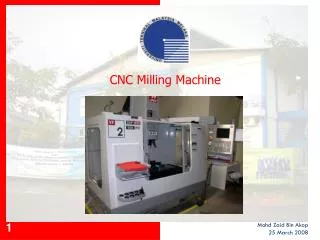
International Journal of Trend in Scientific Research and Development (IJTSRD) Volume 3 Issue 6, October 2019 Available Online: www.ijtsrd.com e-ISSN: 2456 – 6470 Design and Structural Analysis of 3 Axis CNC Milling Machine Table Nyein Chan, Than Zaw Oo, Aung Myo San Hlaing Department of Mechanical Engineering, Technological University, Taunggyi, Myanmar ABSTRACT In the field of Engineering, the solution of many complex problems is great limitless and usually impossible by analytical methods. For high exactness and repeatability, machine tools are used in industrial operation. Normally, several components such as base, knee, saddle, machine table, column and headstock, column are the main parts of the machine tools to get reliable performance. The work piece is held and supported on the machine table. A machine table should be enough rigid and must have good mechanical properties, to obtain a good finished and accurate work piece on a three axis CNC milling machine. A finite element analysis (FEA) gives a methodical study of failure principle which helps for additional progress of the 3 axis machine tables. In this paper, Static Analysis is performed on machine table to find out stresses generated in table, deformation of the table due to its weight. The finite element analysis is done by making 3D geometry in Solidworks software and analyse by using ANSYS software. The material comparison is shown in table and Grey Cast Iron is more dependable than other materials. KEYWORDS: ANSYS 17, deformation, machine table, stress, strain, Solidworks How to cite this paper: Nyein Chan | Than Zaw Oo | Aung Myo San Hlaing "Design and Structural Analysis of 3 Axis CNC Milling Machine Table" Published in International Journal of Trend in Scientific Research and Development (ijtsrd), ISSN: 2456- 6470, Volume-3 | Issue-6, October 2019, pp.943-948, URL: https://www.ijtsrd.com/papers/ijtsrd29 197.pdf Copyright © 2019 by author(s) and International Journal of Trend in Scientific Research and Development Journal. This is an Open Access article distributed under the terms of the Creative Commons Attribution License (http://creativecommons.org/licenses/b y/4.0) IJTSRD29197 (CC BY 4.0) I. A machine table is used for the component to hold and support the work piece. To gain a good finished and precise work piece on the three axis CNC milling machine, a table should be adequate rigid and must have good mechanical properties. A finite element analysis (FEA) gives a methodical study of failure principle, which helps for further development of the three axis machine tables. While machining, three axis CNC machine table is the rectangular casting positioned on the base which supports the fixtures & the work piece. The working table establish on ways on the saddle. The top of the table is correctly finished and t-slots are good for clamping the work and other fixtures on it. The table fixed on machine structure takes vertical forces of work piece and fixtures. [1] The dynamics of the specific machining process and nature of the forces involved, the appropriate design of machine- tool structures needs a exhaustive knowledge of their forms designs and properties of the material. Freshly, examinations have been shown in the field of upgrading of structural design of machine tools by improving stiffness and lightening weight which is especially urgent for the structural parts, such as base, knee, bed, column, worktable, headstock, etc. The prearrangement of stiffening-ribs in machine tool structures is a key feature for structural stiffness and material consumption. So the reducing design of stiffening-ribs is important for machining performance and energy saving. It is usually accepted that the precision of machine tools is resolute by their static, dynamic and INTRODUCTION: thermal characteristics show an significant role in high speed, precision machine tool structures, because vibration during the machining process results in chatter marks on the machined surface and thus creates a noisy environment. High static stiffness in contradiction of bending and torsion, good dynamic characteristics as reflected by high natural frequency and high damping ratio. In production, good long term dimensional stability, reasonably low coefficient of expansion, low cost and low material requirements are the elementary properties of machine tool structures that engineers look for designing and constructing. At current the machine beds are made of grey cast iron material, which cause a number of problems in machine tools. Cast iron cannot with stand the sudden loads during operation whenever the load spreads ultimate loads it simply fails without any previous suggestion. Casting is only the manufacturing process used to produce the beds. This process leads to various casting defects in the component. So as to have high strength and high stiffness the weight of the machine bed should be high. [3] II. Literature Survey Parag R. Bhingardeve et. al studied Static Structural Analysis is performed on machine table to find out stresses performed in table, falsification of the table due to its weight. The FEA is performed by making 3D geometry in CATIA software and analyse by using ANSYS software. characteristics. Specially, the dynamic @ IJTSRD | Unique Paper ID – IJTSRD29197 | Volume – 3 | Issue – 6 | September - October 2019 Page 943
International Journal of Trend in Scientific Research and Development (IJTSRD) @ www.ijtsrd.com eISSN: 2456-6470 Aleksandar Košaracet. al analysed dynamics characteristics of machine tools, especially modal parameters, have significant effect on the cutting procedure and cutting precision. Dynamic behaviour and purpose of modal parameter are shown for horizontal milling centres. For this purposes 3D CAD model of horizontal milling centre has been created using CATIA software, and modal analysis (natural frequencies and mode shapes of the machine tool structure) has been conducted by ANSYS Workbench and APDL. Results gained by FEM modal analysis are validate by experimental modal analysis. Modal parameters obtained experimentally and by FEM are compared, and results shows satisfactory matching. Sagar Pandit Mahajan studied, the conventional structural materials used in precision machine tools such as cast iron and steel at high operating speeds develop positional errors due to the vibrations transferred into the structure. Faster cutting speeds can be developed only by structure which has high stiffness and good restraining characteristics. In this work, a machine bed is selected for the analysis static loads. Then investigation is carried out to decrease the weight of the machine bed without weakening its structural rigidity. The 3D CAD model of the bed has been created by using 3D modelling software and analyses were carried out using ANSYS Workbench. Pratik Bhambhatt et. al studied by using practical data of CNC Router structure, equipped 3D CAD model for Finite Element Analysis in Solid Works 2015. From analysis result find value of von mises stress, strain and displacement (deflection) for optimize structure in strength and cost. Sriranga V Deshpande et. al presented the design and fabrication of 3-axis milling machine. To produce pulse- width modulation (PWM) outputs in order to run the stepper motors that will be used in this work, Computer numerically- controlled (CNC) machine will be comprised the use of Arduino micro controller. A three-axis CNC milling was formerly used exactly surfaced designed for snapping of wood, plastic sheet and thin sheet of metal alloy by using a rotating drill bit which its accuracy was much lesser than using a lesser cutter technique this machine tool was transportable and it’s controlled by the personal computer. Design and Construction of CNC with precision Stepper motors that contacted with the lead screw moment along three-axis. Vedprakash et. al reviewed the sequence of works that have been carried out by different researchers on design, analysis, implementation and construction of a computer numerical controlled (CNC) mechanical systems. The main objective of this paper was to permit the future researchers to provide a passage into the work to improve the performance, accuracy, efficiency and the design of CNC machine. Seyed reza besharati researched, simultaneous motion of the gantry and worktable was projected as the gantry machine’s X-axis double motion mechanism. The double motion mechanism was designed based on a rack and pinion system. A new anti-backlash system is recommended to compensate for transmission error and backlash (simultaneously) and for use in the double motion mechanism. Due to manufacturing boundaries of the rack and pinion systems, a new double motion mechanism based on a ball screw system is proposed. The dynamic and static behaviour of the final CNC gantry machine design is investigated via modal and static structural analysis using ANSYS software. The gantry’s natural frequency was designed to be 202 Hz in the first vibration mode, making the machine capable of working at higher speeds of up to 11530 rpm, which is appropriate not only for rough cutting but also for finishing. The final design of the new CNC gantry machine is updated according to the obtained results. The increase in natural frequency during gantry design modification affects complexity, increasing the weight and manufacturing cost of the gantry. As such, five different gantry designs are selected for comparison. Four parameters, i.e., the first four natural frequencies, total deformation due to mechanical forces, weight and manufacturing cost are measured performance indices. One is selected among five designs mathematically and improved by MOGA (multi-objective genetic algorithm) in ANSYS software. In the optimization process, the gantry’s natural frequency is maximized, thus minimizing the total gantry weight and deformation against mechanical forces. CNC gantry machine documents for manufacturing are equipped, followed by modelling, casting, machining and assembly. To estimate and confirm the design and analysis, an investigational modal test is performed. The tentative results show less than 11% error between the dynamic analysis and investigational test. III. Material and Method reciprocal and Fig. 1 Design Flow Chart MATERIAL USED STRUCTURE IV. FOR MACHINE TOOL The productivity and precision of the part manufactured in structural materials used in a machine tool have a significant role. Material selection is a significant of quality and cost. The properties of the material must be acceptable to meet @ IJTSRD | Unique Paper ID – IJTSRD29197 | Volume – 3 | Issue – 6 | September - October 2019 Page 944
International Journal of Trend in Scientific Research and Development (IJTSRD) @ www.ijtsrd.com eISSN: 2456-6470 design necessities and service conditions. Most commonly used material for machine tool structure is cast iron and steel. Cast Iron Cast iron is mainly an alloy of iron, carbon, and silicon. From primary times cast iron has been the most commonly used material for machine tool structures. It may be cast into complex and complex shapes. It is easily machined and may be hand scraped and lapped to a high degree of accuracy. It has fairly good damping properties and also has reasonably good antifriction properties helped by the graphite contained in it. It can be given very good long-term dimensional stability by giving it a special long cycle stress relief annealing treatment. Cast iron should be preferred for complex structures subjected to normal loading, when these structures are to be made large in numbers. Structural steel The main condition in the selection and inspection of the steel is the tensile strength which is used as the basis of design. Generally load carrying welded structures such as frames, beds, and column. Steel Steel is very widely used for machine components as it can be manufactured and processed into a number of different specifications each of which has a definite use. Two properties of steel apart from strength are of special significance in selection of proper grade of steel. First, the maximum hardness that can be attained and second, the harden ability which regulates the depth of hardened zone. V. Design Consideration A 3D model of the CNC machine bed, its supporting rib and a workpiece for real time analysis was created in SolidWorks 2017 of the dimensions: Table1 Dimensions of CNC Milling Machine Table Dimension (mm) Length ✕ ✕ ✕ ✕ Breadth ✕ ✕ ✕ ✕ Depth 500 ✕ 200 ✕ 50 Model Work piece 1000 ✕ 300 ✕ 141.06 Table 381 ✕ 350 ✕ 78.14 Saddle 304.8 ✕ 500 ✕ 396.875 Knee VI. Firstly, the design model is imported from Solid Works to ANSYS 17. Mesh size is 5mm and node points and element size are 4264771 & 2798773 respectively. Material is Grey Cast Iron. Display style is orthogonal quality and the 3D view of mesh, Total Deformation, Equivalent Stress, Equivalent Strain and Maximum Principal Stress are as follow: Design Analysis Fig.3 Mesh of a Milling Machine Fig. 4 Total Deformation of a Milling Machine Fig.2 Isometric View of CNC Milling Table Fig. 5 Equivalent Stress of a Milling Machine Fig. 3 Side View of CNC Milling Table @ IJTSRD | Unique Paper ID – IJTSRD29197 | Volume – 3 | Issue – 6 | September - October 2019 Page 945
International Journal of Trend in Scientific Research and Development (IJTSRD) @ www.ijtsrd.com eISSN: 2456-6470 Fig. 6 Elastic Strain of a Milling Machine Fig. 10 Equivalent Stress of a Milling Machine Fig. 7 Maximum principle stress of a Milling Machine Fig. 11 Elastic Strain of a Milling Machine Secondly, the design model is imported from SolidWorks to ANSYS 17. Mesh size is 5mm and node points and element size are 4264150 & 2798383 respectively. Material is Structural Steel (ANSI 304). Display style is orthogonal quality and the 3D view of mesh, Total Deformation, Equivalent Stress, Equivalent Strain and Maximum Principal Stress are as follow: Fig. 12 Maximum principle stress of a Milling Machine Finally, the design model is imported from SolidWorks to ANSYS 17. Mesh size is 5mm and node points and element size are 4260551 & 2795635 respectively. Material is Structural Steel (ANSI 1045). Display style is orthogonal quality and the 3D view of mesh, Total Deformation, Equivalent Stress, Equivalent Strain and Maximum Principal Stress are as follow: Fig. 8 Mesh of a Milling Machine Fig. 9 Total Deformation of a Milling Machine Fig.13 Mesh of a Milling Machine @ IJTSRD | Unique Paper ID – IJTSRD29197 | Volume – 3 | Issue – 6 | September - October 2019 Page 946
International Journal of Trend in Scientific Research and Development (IJTSRD) @ www.ijtsrd.com eISSN: 2456-6470 Fig. 14 Total Deformation of a Milling Machine Fig. 16 Elastic Strain of a Milling Machine Fig. 15 Equivalent Stress of a Milling Machine Fig. 17 Maximum principle stress of a Milling Machine Table2. Comparison between Material Result ANSI 304 1.1335e-5 0.034248 2.2849e-7 0.020747 Sr. No. Description Gray Cast Iron 1.8601e-5 0.027891 4.986e-7 0.0070949 ANSI 1045 2.06e-5 0.074173 4.9943e-7 0.041219 1. 2. 3. 4. Total Deformation (mm) Equivalent Stress (MPa) Elastic Strain (mm/mm) Maximum Principal Stress (MPa) VII. From the above tables and figures, the results are shown. As a result, Total Deformation of Grey Cast Iron is less than ANSI 1045 Steel but it is greater than ANSI 304 (Mild Steel). Equivalent Stress, Elastic Strain and Maximum Principal Stress are 0.02789, 4.985e-7 and 0.0070949 respectively. So, for CNC Machine Table, Grey Cast Iron is more reliable than other materials. ACKNOWLEDGMENT A special thanks is offered to Dr. San San Yee, Rector, Technological University (Taunggyi), for her encouragement, constructive guidance and kindly advise throughout the preparation of this research. A special thanks is offered to Dr. Nang Woe Swam, Professor and Head of Mechanical Engineering Department, Technological University (Taunggyi), for her encouragement, constructive guidance and kindly advise throughout the preparation of this research. The author especially would like to take this opportunity to express my sincere gratitude, respect and regards for his Conclusion colleges, U Than Zaw Oo and U Aung Myo San Hlaing, Lecturers, Department of Technological University (Taunggyi), with the help of their guidance, constant encouragement, patient and trust, I have worked on this research. REFERENCES [1]Parag R. Bhingardeve, Rajani T. More, Sujit S. Malgave, “Static structural analysis of 3 axis cnc machine table using finite element analysis”, International Journal of Advanced Technology Science,October 2016 Mechanical Engineering, in Engineering and [2]Aleksandar mladenovic, aleksandar zivkovic, “Modal analysis of a horizontal machining center” kosarac, milan zeljkovic, cvijetin [3]Sagar Pandit Mahajan, Nitin A. Kharche, Yogesh Kharche, “CNC Milling Bed Modelling and Analysis with Composite Material”, interdisciplinary innovative research and development, Vol. 1. Issue 1, 06/2016 International journal of @ IJTSRD | Unique Paper ID – IJTSRD29197 | Volume – 3 | Issue – 6 | September - October 2019 Page 947
International Journal of Trend in Scientific Research and Development (IJTSRD) @ www.ijtsrd.com eISSN: 2456-6470 [4]Pratik Bhambhatt, Mr.Piyush Surani, Mr.Dhaval P Patel, Amarishkumar J.Patel, Sunilkumar N.Chaudhari, “Design and analysis of base structure of CNC router”, JETIR, April 2017, Volume 4, Issue 04 drive system”, Faculty of engineering University of Malaya, Kuala Lumpur, 2015 [8]B. Malleswara Swami1, K.Sunil Ratna Kumar, “Design and structural analysis of CNC vertical Milling machine Bed”, International Journal of Advanced Engineering Technology, IJAET/Vol.III/ 2012/97-100 [5]Sriranga V Deshpande, P U Karthik, Naveen Kumar D, Dr Vijendra Kumar, Dr K. S Badrinaryan, “Design and fabrication of 3-axis International Journal of Engineering Research and General Science Volume 6, Issue 4, July-August, 2018 Issue IV/Oct.-Dec., CNC Milling machine”, [9]Nikunj Aadeshra#1, Prof. R. L. Patel, “Static and Dynamic Analysis of Base of Vertical Machining Center - A Review”, International Journal of Engineering Trends and Technology (IJETT) – Volume 21 Number 9 – March 2015 [6]Vedprakash, Saurabh Sharma, Ashwani Kumar, Priya Kumari, Shyam Lal, “Design and implementation of cnc router: a review”, International Journal of Advanced Research in Science and Engineering, Volume no. 06, Special Issue no. 02, December, 2017 [10]Venkata Ajay Kumar. G, V. Venkatesh, “Modelling and Analysis of CNC Milling Machine Bed with Composite Material”, IJSRD - International Journal for Scientific Research & Development| Vol. 2, Issue 09, 2014 | ISSN (online): 2321-0613 [7]Seyed reza besharati, “Design and manufacturing of a new CNC gantry machine with double motion feed @ IJTSRD | Unique Paper ID – IJTSRD29197 | Volume – 3 | Issue – 6 | September - October 2019 Page 948