Download
1 / 8
80 likes | 82 Views
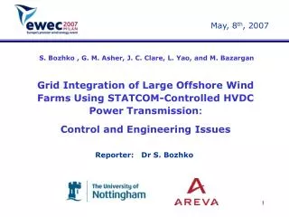
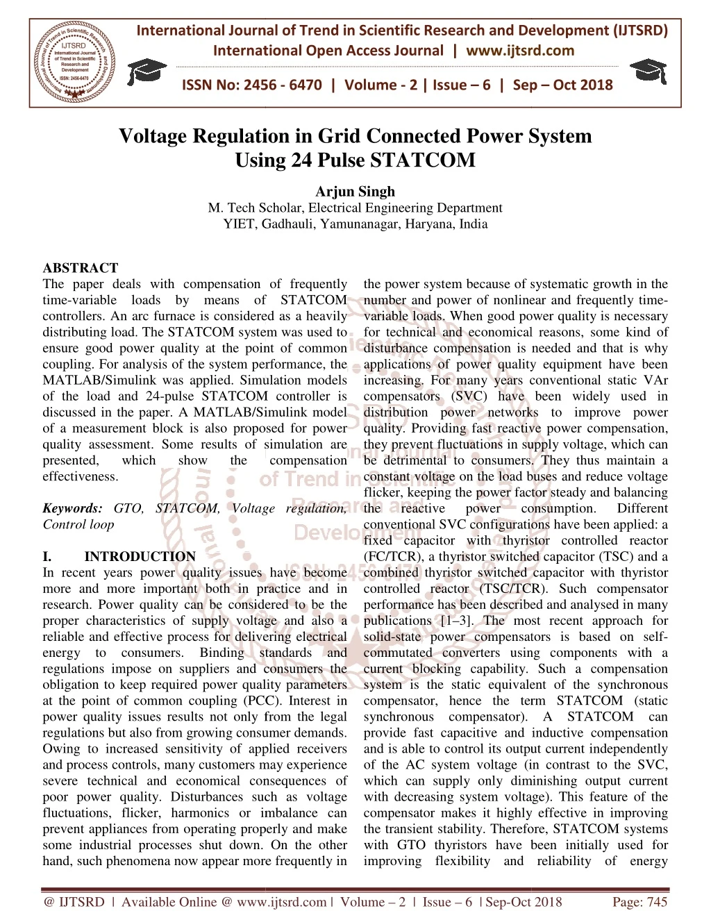
The paper deals with compensation of frequently time variable loads by means of STATCOM controllers. An arc furnace is considered as a heavily distributing load. The STATCOM system was used to ensure good power quality at the point of common coupling. For analysis of the system performance, the MATLAB Simulink was applied. Simulation models of the load and 24 pulse STATCOM controller is discussed in the paper. A MATLAB Simulink model of a measurement block is also proposed for power quality assessment. Some results of simulation are presented, which show the compensation effectiveness. Arjun Singh "Voltage Regulation in Grid Connected Power System Using 24 Pulse STATCOM" Published in International Journal of Trend in Scientific Research and Development (ijtsrd), ISSN: 2456-6470, Volume-2 | Issue-6 , October 2018, URL: https://www.ijtsrd.com/papers/ijtsrd18730.pdf Paper URL: http://www.ijtsrd.com/engineering/electrical-engineering/18730/voltage-regulation-in-grid-connected-power-system-using-24-pulse-statcom/arjun-singh<br>

E N D
International Journal of Trend in International Open Access Journal International Open Access Journal | www.ijtsrd.com International Journal of Trend in Scientific Research and Development (IJTSRD) Research and Development (IJTSRD) www.ijtsrd.com ISSN No: 2456 ISSN No: 2456 - 6470 | Volume - 2 | Issue – 6 | Sep 6 | Sep – Oct 2018 Voltage Regulation in Grid Connected Power System Using 24 Pulse STATCOM Using 24 Pulse STATCOM Regulation in Grid Connected Power System Regulation in Grid Connected Power System Arjun Singh M. Tech Scholar, Electrical Engineering Department YIET, Gadhauli YIET, Gadhauli, Yamunanagar, Haryana, India Tech Scholar, Electrical Engineering Department ABSTRACT The paper deals with compensation of frequently time-variable loads by means of STATCOM controllers. An arc furnace is considered as a heavily distributing load. The STATCOM system was used to ensure good power quality at the point of common coupling. For analysis of the system performance, the MATLAB/Simulink was applied. Simulation models of the load and 24-pulse STATCOM controller is discussed in the paper. A MATLAB/Simulink model of a measurement block is also proposed for power quality assessment. Some results of simulation are presented, which show effectiveness. Keywords:GTO, STATCOM, Voltage regulation, Control loop I. INTRODUCTION In recent years power quality issues have become more and more important both in practice and in research. Power quality can be considered to be the proper characteristics of supply voltage and also a reliable and effective process for delivering electrica energy to consumers. Binding standards and regulations impose on suppliers and consumers the obligation to keep required power quality parameters at the point of common coupling (PCC). Interest in power quality issues results not only from the legal regulations but also from growing consumer demands. Owing to increased sensitivity of applied receivers and process controls, many customers may experience severe technical and economical consequences of poor power quality. Disturbances such as voltage fluctuations, flicker, harmonics or imbalance can prevent appliances from operating properly and make some industrial processes shut down. On the other hand, such phenomena now appear more frequently in hand, such phenomena now appear more frequently in the power system because of systematic growth in the number and power of nonlinear and frequently time variable loads. When good power quality is necessary for technical and economical reasons, some kind of disturbance compensation is needed and that is why applications of power quality equipment have been increasing. For many years conventional static VAr compensators (SVC) have been widely used in distribution power networks to improve power quality. Providing fast reactive power compensation, they prevent fluctuations in supply voltage, which can be detrimental to consumers. They thus maintain a constant voltage on the load buses and reduce voltage flicker, keeping the power factor steady and balancing the reactive power conventional SVC configurations have been applied: a fixed capacitor with thyristor controlled reactor (FC/TCR), a thyristor switched capacitor (TSC) and a combined thyristor switched capacitor with thyristor controlled reactor (TSC/TCR). Such compensator performance has been described and analysed in many publications [1–3]. The most recent approach for solid-state power compensators is based on self commutated converters using components with a current blocking capability. Such a compensation system is the static equivalent of the synchronous compensator, hence the term ST synchronous compensator). A STATCOM can provide fast capacitive and inductive compensation and is able to control its output current independently of the AC system voltage (in contrast to the SVC, which can supply only diminishing output with decreasing system voltage). This feature of the compensator makes it highly effective in improving the transient stability. Therefore, with GTO thyristors have been initially used for improving flexibility and reliability of en improving flexibility and reliability of energy The paper deals with compensation of frequently variable loads by means of STATCOM controllers. An arc furnace is considered as a heavily distributing load. The STATCOM system was used to quality at the point of common coupling. For analysis of the system performance, the MATLAB/Simulink was applied. Simulation models pulse STATCOM controller is discussed in the paper. A MATLAB/Simulink model the power system because of systematic growth in the r and power of nonlinear and frequently time- variable loads. When good power quality is necessary for technical and economical reasons, some kind of disturbance compensation is needed and that is why applications of power quality equipment have been sing. For many years conventional static VAr compensators (SVC) have been widely used in distribution power networks to improve power quality. Providing fast reactive power compensation, they prevent fluctuations in supply voltage, which can to consumers. They thus maintain a constant voltage on the load buses and reduce voltage flicker, keeping the power factor steady and balancing the reactive power conventional SVC configurations have been applied: a with thyristor controlled reactor (FC/TCR), a thyristor switched capacitor (TSC) and a combined thyristor switched capacitor with thyristor controlled reactor (TSC/TCR). Such compensator performance has been described and analysed in many ]. The most recent approach for state power compensators is based on self- commutated converters using components with a current blocking capability. Such a compensation system is the static equivalent of the synchronous compensator, hence the term STATCOM (static synchronous compensator). A STATCOM can provide fast capacitive and inductive compensation and is able to control its output current independently of the AC system voltage (in contrast to the SVC, which can supply only diminishing output current with decreasing system voltage). This feature of the compensator makes it highly effective in improving the transient stability. Therefore, STATCOM systems with GTO thyristors have been initially used for o proposed for power quality assessment. Some results of simulation are presented, which show the the compensation compensation consumption. consumption. Different Different GTO, STATCOM, Voltage regulation, In recent years power quality issues have become more and more important both in practice and in research. Power quality can be considered to be the proper characteristics of supply voltage and also a reliable and effective process for delivering electrical energy to consumers. Binding standards and regulations impose on suppliers and consumers the obligation to keep required power quality parameters at the point of common coupling (PCC). Interest in power quality issues results not only from the legal lations but also from growing consumer demands. Owing to increased sensitivity of applied receivers and process controls, many customers may experience severe technical and economical consequences of poor power quality. Disturbances such as voltage tions, flicker, harmonics or imbalance can prevent appliances from operating properly and make some industrial processes shut down. On the other @ IJTSRD | Available Online @ www.ijtsrd.com www.ijtsrd.com | Volume – 2 | Issue – 6 | Sep-Oct 2018 Oct 2018 Page: 745
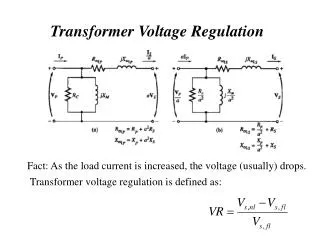
International Journal of Trend in Scientific Research and Development (IJTSRD) ISSN: 2456 of Trend in Scientific Research and Development (IJTSRD) ISSN: 2456 of Trend in Scientific Research and Development (IJTSRD) ISSN: 2456-6470 transmission in FACTS (flexible AC transmission system) applications [4–7]. As the switching frequency of GTOs must be kept low, the control with fundamental frequency switching has been used and multi-phase configurations have been formed to reduce harmonics production. The newest applications of STATCOMs concern power quality improvement at distribution network level. Some examples given in the literature are the reduction of flicker, voltage control and balancing single phase load [6,8]. These are systems of a smaller power where IGBT or IGCT technology can be applied, allowing fast switching with PWM control. Although the possibility of using STATCOMs for the reduction of influence of disturbing loads on the supply network has already been proved in practice, there is still a lack of information about the complex assessment of compensation effectiveness and a method of system selection and its control for a given network. Thus, the purpose of the authors’ work was to develop a model of the system consisting of supply network, disturbing load and STATCOM compensator and the simulation tool enabling selection of the compensator settings and examination of the compensation effectiveness. An arc furnace was selected as a representative example of a heavily disturbing load, which can deteriorate power quality in the grid, particularly components, incorporating the applicable criteria that follow because the power of such devices may be significant. It was assumed that the STATCOM task was to maintain good p at the PCC and provide quality indexes according to the binding standards. The MATLAB/Simulink was selected for simulation, which is particularly useful in the case of networks with power electronics elements and systems [9, 10]. In this paper a MATLAB model is discussed for the system, including supply network, arc furnace as a heavily disturbing load, controller, and a special measurement system for power quality assessment. As there are many configurations of the STATCOM systems, the also different control strategies. In multi systems the method of switching with line frequency is usually used. The authors applied this type of control to the examined network, adopting first the solution given in [10] which realises reactiv control with a PI controller. A number of simulations proved that it can ensure sufficiently good STATCOM operation only for symmetrical, and not for very fast, voltage disturbances. Therefore, a new control circuit has been proposed, which appears more suitable for distribution networks supplying more suitable for distribution networks supplying transmission in FACTS (flexible AC transmission unbalance and frequently time variable loads. It combines two control types: the control of AC voltage and of inverter capacitor voltage. Description of the models developed and some results of simulation are unbalance and frequently time variable loads. It combines two control types: the control of AC voltage and of inverter capacitor voltage. Description of the models developed and some results of simul presented in this paper. II. Modelling of STATCOM The main component of the STATCOM is a VSI (voltage source inverter),which is connected to the network through an inductance,usually of the coupling transformer. The most basic is a six system configuration,giving the rectangular output voltage. As such a system produces harmonics,its practical application is limited. A multi is one of the solutions used for harmonic reduction, in which several identical six connected to transformers having outputs that are phase displaced with respect to one another. Star delta-connected windings give a relative 30 degree phase shift and,with two six- connected,allow 12-pulse STATCOM operation to be obtained. The 24-pulse configuration is an extension of the previous one and consists of four six GTO bridges,connected in parallel and supplied in pairs from the two transformers with primary windings connected in zig zag and secondary windings connected in star and delta. In this way one can obtain the 15 degree phase shift between secondary voltages. For the 24 unit the component single phase 4 winding UMEC transformer was used,which is available in the PSCAD library. Converter bridges were represented using switching device components power electronic switch,which enable both diode and the GTO thyristor to be obtainied together with its snubber circuit. A diagram of the 12-pulse STATCOM and its control circuit in a graphical form obtained in the PSCAD environment is presented in Fig. 3. Components of the CSMF module (control system modelling function) were applied in the special block designed for generating firing pulses. These components return the firing pulse and the interpolation time required III. Operating principle of STATCOM Per phase equivalent circuit is shown in Figure1. Where VG is ac source voltage, VC is STATCOM output voltage, Ic is the current drawn by STATCOM and LT is transformer leakage inductance and `RT’ the resistance that represents the losses of the system [8-11]. 7]. As the switching frequency of GTOs must be kept low, the control with fundamental frequency switching has been used and phase configurations have been formed to armonics production. The newest applications of STATCOMs concern power quality improvement at distribution network level. Some examples given in the literature are the reduction of flicker, voltage control and balancing single phase load [6,8]. These ystems of a smaller power where IGBT or IGCT technology can be applied, allowing fast switching with PWM control. Although the possibility of using STATCOMs for the reduction of influence of disturbing loads on the supply network has already practice, there is still a lack of information about the complex assessment of compensation effectiveness and a method of system selection and its control for a given network. Thus, the purpose of the authors’ work was to develop a sisting of supply network, disturbing load and STATCOM compensator and the simulation tool enabling selection of the compensator settings and examination of the compensation effectiveness. An arc furnace was selected as a Modelling of STATCOM The main component of the STATCOM is a VSI (voltage source inverter),which is connected to the network through an inductance,usually of the coupling transformer. The most basic is a six-pulse configuration,giving the rectangular output voltage. As such a system produces harmonics,its practical application is limited. A multi-pulse scheme is one of the solutions used for harmonic reduction, in which several identical six-pulse bridges are ted to transformers having outputs that are phase displaced with respect to one another. Star- and connected windings give a relative 30 degree -pulse converter bridges pulse STATCOM operation to be pulse configuration is an extension of the previous one and consists of four six-pulse GTO bridges,connected in parallel and supplied in pairs from the two transformers with primary windings connected in zig- ondary windings connected in star and delta. In this way one can obtain the 15 degree phase shift between secondary voltages. For the 24-pulse unit the component single phase 4 winding UMEC transformer was used,which is available in the erter bridges were represented using switching device components power electronic switch,which enable both diode and the GTO thyristor to be obtainied together with its snubber circuit. A pulse STATCOM and its control al form obtained in the PSCAD environment is presented in Fig. 3. Components of the CSMF module (control system modelling function) were applied in the special block designed for generating firing pulses. These components return the terpolation time required. threewindings threewindings converter converter y disturbing load, which can deteriorate power quality in the grid, particularly components, incorporating the applicable criteria that follow because the power of such devices may be significant. It was assumed that the STATCOM task was to maintain good power quality at the PCC and provide quality indexes according to the binding standards. The MATLAB/Simulink was selected for simulation, which is particularly useful in the case of networks with power electronics elements MATLAB model is discussed for the system, including supply network, arc furnace as a heavily disturbing load, STATCOM controller, and a special measurement system for power quality assessment. As there are many configurations of the STATCOM systems, there are also different control strategies. In multi-phase systems the method of switching with line frequency is usually used. The authors applied this type of control to the examined network, adopting first the solution given in [10] which realises reactive power control with a PI controller. A number of simulations proved that it can ensure sufficiently good STATCOM operation only for symmetrical, and not for very fast, voltage disturbances. Therefore, a new control circuit has been proposed, which appears to be Operating principle of STATCOM Per phase equivalent circuit is shown in Figure1. Where VG is ac source voltage, VC is STATCOM output voltage, Ic is the current drawn by STATCOM and LT is transformer leakage inductance and `RT’ is the resistance that represents the losses of the system @ IJTSRD | Available Online @ www.ijtsrd.com www.ijtsrd.com | Volume – 2 | Issue – 6 | Sep-Oct 2018 Oct 2018 Page: 746
International Journal of Trend in Scientific Research and Development (IJTSRD) ISSN: 2456 of Trend in Scientific Research and Development (IJTSRD) ISSN: 2456 of Trend in Scientific Research and Development (IJTSRD) ISSN: 2456-6470 fundamental and high-order harmonics, and may be represented as: e = ef+ en1+en2 e = ef + ∑ ei i= n1, n2... Where ef, is the RMS value of the fundamental harmonic, ei, represents the RMS harmonics, and n1, n2 are the harmonic indices. Thus, the first diagram of Fig 2 can be represented as the sum of the other harmonic diagrams.[8] Ploss = Pfundamental + Pharmonic A.CONTROL OF REACTIVE POWER It is well known that the amount and type (capacitive or inductive) of reactive power exchange between the STATCOM and the system can be adjusted by controlling the magnitude of STATCOM output voltage with respect to that of system voltage. The reactive power supplied by the STATCOM is given by Equation below:- Q = (Vstatcom-Vs)/X Where VSTATCOM, and Vs, are the magnitudes of STATCOM output voltage and system voltage respectively and X is the equivalent impedance between STATCOM and the system. When Q is positive, the STATCOM supplies reactive power to the system. Otherwise, the STATCOM absorbs reactive power from the system. B.CONTROL OF DC CAPACITOR VOLTAGE If all the components were ideal and the STATCOM output voltage were exactly in phase with the system voltage, there would have been no real power exchange between STATCOM and system therefore the voltages across the DC capacitors would have been able to sustain. However, a slight phase difference between the system voltage STATCOM output voltage is always needed to supply a small amount of real power to the STATCOM to compensate the component loss so that the DC capacitor voltages can be maintained. This slight phase difference is achieved by adjusting the phase angle of the sinusoidal modulating signal. If the real power delivered to the STATCOM is more than its total component loss, the DC capacitor voltage will rise, and vice versa. The real power exchange between STATCOM and the system is described by Equation (5) below:- Sin V V P = order harmonics, and may be (1) (2) Where ef, is the RMS value of the fundamental harmonic, ei, represents the RMS values of high-order harmonics, and n1, n2 are the harmonic indices. Thus, the first diagram of Fig 2 can be represented as the sum of the other harmonic diagrams.[8] Fig -1: Equivalent circuit diagram of STATCOM [1] : Equivalent circuit diagram of STATCOM [1] The STATCOM is basically a DC-AC voltage source converter with an energy storage unit, usually a DC capacitor. It operates as a controlled Synchronous Voltage Source (SVS) connected to the line through a coupling transformer. Fig. 1 shows the Equivalent circuit diagram of STATCOM. The controlled output voltage is maintained in phase with the line voltage, and can be controlled to draw either capacitive or inductive current from the line in a similar manner of a synchronous condenser, but much more rapidly. STATCOM has the ability to maintain full capacitive output current at low system voltage, which also improving the transient stability. Basically, a STATCOM output voltage always contains harmonics, due to the switching behavior of the VSI. These voltage harmonics will generate harmonic currents and further cause power losses in the system network. If the impedance of the lines that connect a STATCOM to the power system is neglected, the harmonic losses are primarily apparent on the connection transformer. The effect of these losses in the transformer can by analyzed by considering an expansion of the transformer. [8] considering an expansion of the transformer. [8] AC voltage source converter with an energy storage unit, usually a DC rmonic (3) ed Synchronous Voltage Source (SVS) connected to the line through a coupling transformer. Fig. 1 shows the Equivalent circuit diagram of STATCOM. The controlled output voltage is maintained in phase with the line voltage, CONTROL OF REACTIVE POWER known that the amount and type (capacitive or inductive) of reactive power exchange between the STATCOM and the system can be adjusted by controlling the magnitude of STATCOM output voltage with respect to that of system voltage. The d by the STATCOM is given er capacitive or inductive current from the line in a similar manner of a synchronous condenser, but much more rapidly. STATCOM has the ability to maintain full capacitive output current at low system voltage, which also Vs)/X (4) Where VSTATCOM, and Vs, are the magnitudes of STATCOM output voltage and system voltage respectively and X is the equivalent impedance and the system. When Q is positive, the STATCOM supplies reactive power to the system. Otherwise, the STATCOM absorbs reactive power from the system. Basically, a STATCOM output voltage always contains harmonics, due to the switching behavior of the VSI. These voltage harmonics will generate harmonic currents and further cause power losses in the system network. If the impedance of the lines that ct a STATCOM to the power system is neglected, the harmonic losses are primarily apparent on the connection transformer. The effect of these losses in the transformer can by analyzed by CONTROL OF DC CAPACITOR VOLTAGE If all the components were ideal and the STATCOM exactly in phase with the system voltage, there would have been no real power exchange between STATCOM and system therefore the voltages across the DC capacitors would have been able to sustain. However, a slight phase difference between the system voltage and the STATCOM output voltage is always needed to supply a small amount of real power to the STATCOM to compensate the component loss so that the DC capacitor voltages can be maintained. This slight phase difference is achieved by adjusting the phase le of the sinusoidal modulating signal. If the real power delivered to the STATCOM is more than its total component loss, the DC capacitor voltage will rise, and vice versa. The real power exchange between STATCOM and the system is described by Equation Fig -2: STATCOM Model for Harmonic losses el for Harmonic losses Fig.2 shows the circuit of a STATCOM connected to a power system by a connection transformer, where V and e represent the system RMS voltage and the STATCOM’s RMS output potential respectively, and RT and XT denote the resistance an reactance of the connection transformer. Assuming that there are not any harmonics in the system voltage V, the STATCOM output voltage e consists of V, the STATCOM output voltage e consists of Fig.2 shows the circuit of a STATCOM connected to a power system by a connection transformer, where V and e represent the system RMS voltage and the STATCOM’s RMS output potential respectively, and RT and XT denote the resistance and leakage reactance of the connection transformer. Assuming that there are not any harmonics in the system voltage δ − S STATCOM (5) X @ IJTSRD | Available Online @ www.ijtsrd.com www.ijtsrd.com | Volume – 2 | Issue – 6 | Sep-Oct 2018 Oct 2018 Page: 747
International Journal of Trend in Scientific Research and Development (IJTSRD) ISSN: 2456 of Trend in Scientific Research and Development (IJTSRD) ISSN: 2456 of Trend in Scientific Research and Development (IJTSRD) ISSN: 2456-6470 Where δ is the phase angle difference between STATCOM voltage and the system voltage. A controllable three-phase AC output voltage waveform close to sinusoidal nature is obtained at the point of common coupling (PCC). The output AC voltage of the VSC(Voltage source converter) is (Vc) is governed by a DC capacitor voltage (Vdc), which can be controlled by varying phase difference ( between Vc and Vs (supply voltage). An almost sinusoidal current in quadrature with the line voltage is injected into the electrical system emulating an inductive or a capacitive reactance at PCC. The magnitude of the quadrature component of the VSC current (Iq) regulates the phase difference ( Vc and Vs across the transformer leakage reactance (X), which in turn controls reactive power flow, Here α is basically is the firing angle. The basic operating principle of a GTO-VSC based STATCOM is that When Vc>Vs, the STATCOM is considered to be operating in a capacitive mode and when Vc < Vs, it is operating in an inductive mode and for Vc = Vs, no reactive power exchange takes place and STATCOM is said to be operating in floating mode. However, a small phase difference (α) is maintained so that VSC losses are compensated by active power drawn from AC system. Applying phase angle control ( Vc and Vs, Vdc is controlled with charging or discharging of the capacitor and thus capacitive or inductive or floating mode of operation is emulated to control reactive power flow in the AC system. 3. SIMULATION AND STATCOM In this paper the concept of new magnetics is evolved to eliminate 5th, 7th harmonics in first stage and in the second stage 11th, 13th and higher order of voltage harmonics and thus, minimizes the THD levels. Inter-facing magnetic is configured in two stages by employing a combination of 3 converter transformer in first stage and a group of two 3-phase PSTs for +15º and -15º phase shifts in the second stage. The two sets of phase-shifted voltage waveforms and output ac voltage waveform from the converter transformer are added electromagnetically to get final output voltages at the point of common coupling (PCC). is the phase angle difference between STATCOM voltage and the system voltage. phase AC output voltage waveform close to sinusoidal nature is obtained at the n coupling (PCC). The output AC voltage of the VSC(Voltage source converter) is (Vc) is governed by a DC capacitor voltage (Vdc), which can be controlled by varying phase difference (α) between Vc and Vs (supply voltage). An almost adrature with the line voltage is injected into the electrical system emulating an inductive or a capacitive reactance at PCC. The magnitude of the quadrature component of the VSC current (Iq) regulates the phase difference (α) between transformer leakage reactance (X), which in turn controls reactive power flow, Here is basically is the firing angle. The basic operating VSC based STATCOM is that When Vc>Vs, the STATCOM is considered to be mode and when Vc < Vs, it is operating in an inductive mode and for Vc = Vs, no reactive power exchange takes place and STATCOM is said to be operating in floating mode. However, a ) is maintained so that VSC by active power drawn from AC system. Applying phase angle control (α) between Vc and Vs, Vdc is controlled with charging or discharging of the capacitor and thus capacitive or inductive or floating mode of operation is emulated to flow in the AC system. Fig -3: Inner current control loop circuit Inner current control loop circuit Fig -4: Outer voltage control loop circuit voltage control loop circuit 3.1. CONTROL OF STATCOM The controller of a STATCOM is used to operate the inverter in such a way that the phase angle between the inverter voltage and the line voltage is dynamically adjusted so that the STATCOM generates or absorbs desired VAR at the point of connection. Fig. 5 shows a simplified diagram of the STATCOM with an inverter voltage source and a tie reactance, XT1E, connected to a system with a voltage source, VTH, and a Thevenin’s reactance XTH , When the inverter voltage is higher than the system voltage, the STATCOM sees” an inductive reactance connected at its terminal. Hence, the system “sees” the STATCOM as a capacitive reactance and the STATCOM is considered to be operating in a capacitive mode. Similarly, when the system voltage is higher than the inverter voltage, the system “sees” an inductive reactance connected at its terminal. Hence, the STATCOM sees the system as a capacitive reactance and the STATCOM is considered to be operating in an inductive mode. operating in an inductive mode. CONTROL OF STATCOM The controller of a STATCOM is used to operate the inverter in such a way that the phase angle between the inverter voltage and the line voltage is dynamically adjusted so that the STATCOM generates or absorbs desired VAR at the point of connection. Fig. 5 shows a simplified diagram of the STATCOM with an inverter voltage source and a tie reactance, XT1E, connected to a system with a voltage source, VTH, and a Thevenin’s reactance, XTH , When the inverter voltage is higher than the system voltage, the STATCOM sees” an inductive reactance connected at its terminal. Hence, the system “sees” the STATCOM as a capacitive reactance and the STATCOM is considered to be capacitive mode. Similarly, when the system voltage is higher than the inverter voltage, the system “sees” an inductive reactance connected at its terminal. Hence, the STATCOM sees the system as a capacitive reactance and the STATCOM is considered SIMULATION AND OPERATION OPERATION OF OF In this paper the concept of new magnetics is evolved to eliminate 5th, 7th harmonics in first stage and in the second stage 11th, 13th and higher order of minimizes the THD facing magnetic is configured in two stages by employing a combination of 3-phase ∆-Υ/Υ converter transformer in first stage and a group of two 15º phase shifts in the shifted voltage waveforms and output ac voltage waveform from the converter transformer are added electromagnetically to get final output voltages at the point of common Fig -5: Static Synchronous Compensator Operated in Capacitive and Inductive Modes. Capacitive and Inductive Modes. Static Synchronous Compensator Operated in @ IJTSRD | Available Online @ www.ijtsrd.com www.ijtsrd.com | Volume – 2 | Issue – 6 | Sep-Oct 2018 Oct 2018 Page: 748
International Journal of Trend in Scientific Research and Development (IJTSRD) ISSN: 2456 of Trend in Scientific Research and Development (IJTSRD) ISSN: 2456 of Trend in Scientific Research and Development (IJTSRD) ISSN: 2456-6470 by adding the relative angle, α of the inverter and fig.4 hows the MATLAB/Simulink system of inner current control loop. The outer voltage control unit maintains the voltage across the dc capacitor equal to a constant reference voltage. Keeping the dc voltage constant simplifies the voltage control scheme shows n fig.4. This control loop system generates the reference current Iq reference and injected in the inner current control loop which further generates the firing based converter and also generates a voltage Vdq; voltage at the dq co- by adding the relative angle, α of the inverter and fig.4 shows the MATLAB/Simulink system of inner current control loop. The outer voltage control unit maintains the voltage across the dc capacitor equal to a constant reference voltage. Keeping the dc voltage constant simplifies the voltage control scheme shows in fig.4. This control loop system generates the reference current Iq reference and injected in the inner current control loop which further generates the firing angle α for the GTO-based converter and also generates a voltage Vdq; voltage at the dq co ordinates. Transformer connection:- The transformer connection used in 24 STATCOM model used to eliminates the 5th,7th harmonics in first stage and in the second stage 11th, 13th and higher order of voltage harmonics and thus, minimizes the THD levels. Inter configured in two stages by employing a combination of 3-phase ∆-Υ/Υ converter transformer in first stage, and a group of two 3-phase PSTs for +15º and phase shifts in the second stage shows in fig.7. phase shifts in the second stage shows in fig.7. Fig -6 Current Control Block Diagram of a Static Synchronous Compensator. Synchronous Compensator. Current Control Block Diagram of a Static Fig. 6 shows the reactive current control block diagram of the STATCOM. An instantaneous 3 phase set of line voltages, v1, at BUS 1 is used to calculate the reference angle, θ, which is phase locked to the phase a of the line voltage, v1a An instantaneous 3- phase set of measured inverter currents, i1 is decomposed into its real or direct component, I1d and component, I1q respectively. The quadrature component is compared with the desired reference value, I1q* and the error is passed through an error amplifier which produces a relative angle, inverter voltage with respect to the line voltage. The phase angle, θ1, of the inverter voltage is calculated 1, of the inverter voltage is calculated Fig. 6 shows the reactive current control block diagram of the STATCOM. An instantaneous 3- phase set of line voltages, v1, at BUS 1 is used to , which is phase- The transformer connection used in 24-pulse STATCOM model used to eliminates the 5th,7th harmonics in first stage and in the second stage 11th, 13th and higher order of voltage harmonics and thus, locked to the phase a of the line voltage, v1a An phase set of measured inverter currents, i1 is decomposed into its real or direct component, I1d and component, I1q respectively. The quadrature component is compared with the desired reference e error is passed through an error amplifier which produces a relative angle, α of the inverter voltage with respect to the line voltage. The reactive reactive or or quadrature quadrature Inter-facing magnetics is configured in two stages by employing a combination converter transformer in first stage, phase PSTs for +15º and -15º Fig -7: Transformer connection for Phase Transformer connection for Phase-shifting. @ IJTSRD | Available Online @ www.ijtsrd.com www.ijtsrd.com | Volume – 2 | Issue – 6 | Sep-Oct 2018 Oct 2018 Page: 749
International Journal of Trend in Scientific Research and Development (IJTSRD) ISSN: 2456 of Trend in Scientific Research and Development (IJTSRD) ISSN: 2456 of Trend in Scientific Research and Development (IJTSRD) ISSN: 2456-6470 Fig Fig -8: 24-Pulse STATCOM Model. 4. RESULTS The reference line voltage V* is set to 1.0pu, 1.03pu, 0.97pu and 1.03pu at the instant of 0s, 0.22s, 0.42s, 0.60s respectively. In the voltage control loop presuming that STATCOM would be operated as a voltage regulator. With the DC capacitor (C) pre charged and total simulation time set at 0.60sec, the performance of the compensator corresponding to a load of 70MW 0.85pf (lag) at 132kV is studied. The voltage waveform is shown in fig.9. From the fig. 9 the variations in the voltage can be clearly seen. I fig.10 shows the voltage at the point of common coupling (PCC). The STATCOM injects the reactive power when the voltage is less than the reference value and vice-versa. The voltage and current spectrum is shown in fig.11 at the point of common Coupling (PCC). The harmonic spectrum for voltage regulation corresponding to the capacitive and inductive mode for voltage and current are shown in figure 10(b), figure 11(b) (For capacitive mode), FFT analysis on the voltage and current harmonic spectrum have been carried out for the compensator and THD levels quantified during its operation for voltage regulation and power factor correction to unity. The reference line voltage V* is set to 1.0pu, 1.03pu, 0.97pu and 1.03pu at the instant of 0s, 0.22s, 0.42s, 0.60s respectively. In the voltage control loop presuming that STATCOM would be operated as a voltage regulator. With the DC capacitor (C) pre- ged and total simulation time set at 0.60sec, the performance of the compensator corresponding to a load of 70MW 0.85pf (lag) at 132kV is studied. The voltage waveform is shown in fig.9. From the fig. 9 the variations in the voltage can be clearly seen. In fig.10 shows the voltage at the point of common coupling (PCC). The STATCOM injects the reactive power when the voltage is less than the reference versa. The voltage and current spectrum is shown in fig.11 at the point of common PCC). The harmonic spectrum for voltage regulation corresponding to the capacitive and inductive mode for voltage and current are shown in figure 10(b), figure 11(b) (For capacitive mode), FFT analysis on the voltage and current harmonic carried out for the compensator and THD levels quantified during its operation for voltage regulation and power factor correction to Fig -9: Three phase instantaneous voltages. Three phase instantaneous voltages. Fig -10(a): Voltage at PCC. : Voltage at PCC. @ IJTSRD | Available Online @ www.ijtsrd.com www.ijtsrd.com | Volume – 2 | Issue – 6 | Sep-Oct 2018 Oct 2018 Page: 750
International Journal of Trend in Scientific Research and Development (IJTSRD) ISSN: 2456 of Trend in Scientific Research and Development (IJTSRD) ISSN: 2456 of Trend in Scientific Research and Development (IJTSRD) ISSN: 2456-6470 sets an electromagnetic coupling with AC system at PCC ( Point of Common Coupling ). These magnetic circuits are also work to mitigate the harmonics of the order of 5th, 7th, 11th, 13th and higher order. This model is designed with two elementary 6-pulse GTO- VSCs connected in parallel across the DC capacitor used as energy storage, and interfacing magnetics configured in two stages. It also contained the tow PI- controllers, one of them is named as inner current control loop and another is outer voltage control loop. The compensator has been simulated to regulate voltage for an inductive load in electrical network as well as power factor correction to unity. Basic operating characteristics of the model as illustrated shows it’s satisfactory and improved performance. sets an electromagnetic coupling with AC system at PCC ( Point of Common Coupling ). These magnetic circuits are also work to mitigate the harmonics of the order of 5th, 7th, 11th, 13th and highe model is designed with two elementary 6 VSCs connected in parallel across the DC capacitor used as energy storage, and interfacing magnetics configured in two stages. It also contained the tow PI controllers, one of them is named as control loop and another is outer voltage control loop. The compensator has been simulated to regulate voltage for an inductive load in electrical network as well as power factor correction to unity. Basic operating characteristics of the mo shows it’s satisfactory and improved performance. As we have seen the performance of STATCOM working as voltage regulation mode as well as unity power factor correction var control mode. And by seeing the results of THDs of voltage and spectrum we can say that STATCOM performs much better while working in voltage regulation mode as compare to the unity power factor correction in var control mode. Although unity power factor correction in var control mode gives satisfactory resul voltage regulation mode of operation mode improve the performance of the STACOM, and is greatly accepted in industrial and power utility applications. 6. APPENDIX Parameters of the GTO-VSC based 24 100 MVAr STATCOM model: 1.STATCOM parameter: Converter type-VSC; Thyristor pulses-24; normal AC voltage voltage-8.3 kv; GTO fixed resistance triggering control –fundamental frequency (50Hz) switching DC capacitor -20000 2.Interfacing magnetic (Base Stage-1 ?Converter transformer: 3-phase 3-winding PST Rating: 1000MVA,50Hz,66Kv/5.1kv,12.8 % (X) Vector group: Y/∆-Y Stage- II ?3-phase 3winding (+)15degree Rating: 100MVA,50Hz,66kV/5.1Kv,12.8 % (X). Stage –II Fig -10(b): Voltage (Va) Spectrum in Capacitive mode (Va) Spectrum in Capacitive As we have seen the performance of STATCOM working as voltage regulation mode as well as unity power factor correction var control mode. And by seeing the results of THDs of voltage and current spectrum we can say that STATCOM performs much better while working in voltage regulation mode as compare to the unity power factor correction in var control mode. Although unity power factor correction in var control mode gives satisfactory results but voltage regulation mode of operation mode improve the performance of the STACOM, and is greatly accepted in industrial and power utility applications. Fig -11(a): VaIa at PCC at PCC VSC based 24-pulse 2-level ± 100 MVAr STATCOM model: VSC; Thyristor-GTO; no. of 24; normal AC voltage-5.1Kv;normal DC 8.3 kv; GTO fixed resistance-0.01Ω GTO fundamental frequency (50Hz) 20000µf. Interfacing magnetic (Base-100MVA): Converter transformer: winding PST Rating: 1000MVA,50Hz,66Kv/5.1kv,12.8 % Fig -11(b): Current (Ia) spectrum in capacitive mode ) spectrum in capacitive 5. CONCLUSIONS A new type of multi-pulse STATCOM having two stages of magnetic circuit is evolved. The first stage of magnetic circuit is used for setting-up VSC output AC voltage to line voltage level, while other magnetic circuit is used for providing phase shift to th voltage of stage-1 magnetic circuits, which in turn 1 magnetic circuits, which in turn pulse STATCOM having two phase 3winding zigzag zigzag connected connected stages of magnetic circuit is evolved. The first stage up VSC output Rating: 100MVA,50Hz,66kV/5.1Kv,12.8 % AC voltage to line voltage level, while other magnetic circuit is used for providing phase shift to the output @ IJTSRD | Available Online @ www.ijtsrd.com www.ijtsrd.com | Volume – 2 | Issue – 6 | Sep-Oct 2018 Oct 2018 Page: 751
International Journal of Trend in Scientific Research and Development (IJTSRD) ISSN: 2456 of Trend in Scientific Research and Development (IJTSRD) ISSN: 2456 of Trend in Scientific Research and Development (IJTSRD) ISSN: 2456-6470 ?3-phase 3- winding zigzag connected(+) 15 degree PST Rating: 25 MVA,50 Hz,33 kv/5.1kv, 10.8%(X),Vector Group: Zigzag or interconnected-star/open-Y ?3-Phase,3-winding degree PST ,Rating:- 25 MVA,50 Hz,33 kv/5.1kv,10.8%(X) interconnected-star/open-Y 3.PI-controller Gains:- Inner Current Controller:-Kp =29, Ki=2000 Outer Voltage Controller: - Kp =70, Ki=1500 4.Thevenin equivalent Voltage Source: Nominal Voltage:-132 kv(rms); Fundamental frequency- 50Hz, Short ckt. Level: MVA; X/R ratio-10 5.Transmission Line:- R=0.1622Ω, L=1.0214e-3H 6.Discrete Sampling Time =5e-6s 7.MATLAB Version-2016 REFERENCES 1.Bhim Singh, R. Saha, “A Harmonics Optimized 12-Pulse STATCOM for Power System Applications”, in proc. IEEE Power India conference, India,2006. 2.Kalyan K. Sen, Compensator:-Theory,Modeling and Application” in 1998 IEEE,PP.-1177-1183. 3.K. R. Padiyar, “FACTS Controllers In Power Transmission and Distribution”, New A dege International Publishers. 4.N. G. Hingorani and L. Gyugyi, Understanding FACTS. New York: IEEE Press, 2000. 5.Carlos A. C. Cavaliere, Edson H. Watanabe, Maurício Aredes, “Multi-pulse ag connected(+) 15 Operation Under Unbalanced Voltages”, 0 7322-7/02/$17.00PP. 567- 6.Luis Moran, Member, Phoivos D. Ziogas, a GezaJoos, “A Solid-state High Reactive-Power Transactions on Industry Applications, VOL. 29, NO. 5, September/October 1993. 7.Ashwin Kumar Sahoo, K. Murugesan and T. Thygarajan, “Modeling and Simulation of 48 pulse VSC Based STATCOM Using Simulink’s Power System Blockset”, Proceedings of India International Conference on Power Electronics 2006. 8.T. Manokaran. B. Sakthivel, S. Mohamed Yousuf, “Cascaded Multi-Level Inverter Based Harmonic Reduction in STATCOM”, International Jo of Engineering Science and Technology Vol. 2(10), 2010, 5424-5431. 9.Diego Soto, Member, Tim C. Green, “A Comparison of Topologies for the Implementation of FACTS Controllers”, IEEE INDUSTRIAL ELECTRONICS, VOL. 4 OCTOBER 2002. 10.B. singh, R. saha, A. Chandra, Staticsynchronous compensator(STATCOM): a review”,IET Power Electron.,Vol.2,Iss.4,pp. 297 324. 11.S. Arockia Edwin Xavier Saravanan: “Development Controllers For Statcom”; Operation Under Unbalanced Voltages”, 0-7803- degree PST Rating: 25 MVA,50 Hz,33 kv/5.1kv, 10.8%(X),Vector Group: Zigzag or -572 © 2002 IEEE. Luis Moran, Member, Phoivos D. Ziogas, and state High-Performance Power Transactions on Industry Applications, VOL. 29, NO. 5, September/October 1993. winding zigzag zigzag connected( connected(-15) 25 MVA,50 Hz,33 Group: Zigzag Compensator”, Compensator”, IEEE IEEE kv/5.1kv,10.8%(X) Group: Zigzag or or Ashwin Kumar Sahoo, K. Murugesan and T. Thygarajan, “Modeling and Simulation of 48- d STATCOM Using Simulink’s Power System Blockset”, Proceedings of India International Conference on Power Electronics Kp =29, Ki=2000 Kp =70, Ki=1500 Thevenin equivalent Voltage Source:- 132 kv(rms); Fundamental 50Hz, Short ckt. Level: - 3000 T. Manokaran. B. Sakthivel, S. Mohamed Yousuf, Level Inverter Based Harmonic Reduction in STATCOM”, International Journal of Engineering Science and Technology Vol. Diego Soto, Member, Tim C. Green, “A Comparison of Topologies for the Implementation of FACTS Controllers”, IEEE INDUSTRIAL ELECTRONICS, VOL. 49, NO. 5, High High-Power Converter Bhim Singh, R. Saha, “A Harmonics Optimized Pulse STATCOM for Power System Applications”, in proc. IEEE Power India TRANSACTIONS TRANSACTIONS ON ON Kalyan K. Sen, “Static “Static Synchronous Synchronous Chandra, K. AL-Haddad; Theory,Modeling and Application” Staticsynchronous compensator(STATCOM): a review”,IET Power Electron.,Vol.2,Iss.4,pp. 297- K. R. Padiyar, “FACTS Controllers In Power Transmission and Distribution”, New A dege Arockia Edwin Xavier, P. Venkatesh, and M. Saravanan: “Development Of Of Intelligent Intelligent Understanding IEEE 2008. FACTS. New York: IEEE Press, 2000. Carlos A. C. Cavaliere, Edson H. Watanabe, pulse STATCOM STATCOM @ IJTSRD | Available Online @ www.ijtsrd.com www.ijtsrd.com | Volume – 2 | Issue – 6 | Sep-Oct 2018 Oct 2018 Page: 752