Download
1 / 8
80 likes | 88 Views
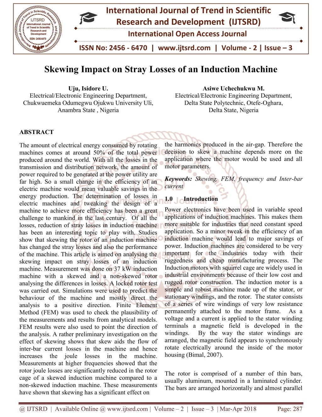
The amount of electrical energy consumed by rotating machines comes at around 50 of the total power produced around the world. With all the losses in the transmission and distribution network, the amount of power required to be generated at the power utility are far high. So a small change in the efficiency of an electric machine would mean valuable savings in the energy production. The determination of losses in electric machines and tweaking the design of a machine to achieve more efficiency has been a great challenge to mankind in the last century. Of all the losses, reduction of stray losses in induction machine has been an interesting topic to play with. Studies show that skewing the rotor of an induction machine has changed the stray losses and also the performance of the machine. This article is aimed on analysing the skewing impact on stray losses of an induction machine. Measurement was done on 37 kW induction machine with a skewed and a non skewed rotor analysing the differences in losses. A locked rotor test was carried out. Simulations were used to predict the behaviour of the machine and mostly direct the analysis to a positive direction. Finite Element Method FEM was used to check the plausibility of the measurements and results from analytical models. FEM results were also used to point the direction of the analysis. A rather preliminary investigation on the effect of skewing shows that skew aids the flow of inter bar current losses in the machine and hence increases the joule losses in the machine. Measurements at higher frequencies showed that the rotor joule losses are significantly reduced in the rotor cage of a skewed induction machine compared to a non skewed induction machine. These measurements have shown that skewing has a significant effect on the harmonics produced in the air gap. Therefore the decision to skew a machine depends more on the application where the motor would be used and all motor parameters. Uju, Isidore U. | Asiwe Uchechukwu M. "Skewing Impact on Stray Losses of an Induction Machine" Published in International Journal of Trend in Scientific Research and Development (ijtsrd), ISSN: 2456-6470, Volume-2 | Issue-3 , April 2018, URL: https://www.ijtsrd.com/papers/ijtsrd10808.pdf Paper URL: http://www.ijtsrd.com/engineering/electrical-engineering/10808/skewing-impact-on-stray-losses-of-an-induction-machine/uju-isidore-u<br>

E N D
International Research Research and Development (IJTSRD) International Open Access Journal n Stray Losses of an Induction Machine International Journal of Trend in Scientific Scientific (IJTSRD) International Open Access Journal ISSN No: 2456 ISSN No: 2456 - 6470 | www.ijtsrd.com | Volume www.ijtsrd.com | Volume - 2 | Issue – 3 Skewing Impact on Stray Losses n Induction Machine Uju, Isidore U. Electronic Engineering Department, Chukwuemeka Odumegwu Ojukwu University Uli, Asiwe Uchechukwu Asiwe Uchechukwu M. Electrical/Electronic Engineering Department, Delta State Polytechnic, Otefe-Oghara, Electrical/Electronic Engineering Department, Chukwuemeka Odumegwu Ojukwu University Uli, Anambra State , Nigeria Electrical/Electronic Engineering Department, Delta State Polytechnic, Otefe Delta State, Nigeria Nigeria ABSTRACT The amount of electrical energy consumed by rotating machines comes at around 50% of the total power produced around the world. With all the losses in the transmission and distribution network, the amount of power required to be generated at the power util far high. So a small change in the efficiency of an electric machine would mean valuable savings in the energy production. The determination of losses in electric machines and tweaking the design of a machine to achieve more efficiency has been a g challenge to mankind in the last century. Of all the losses, reduction of stray losses in induction machine has been an interesting topic to play with. Studies show that skewing the rotor of an induction machine has changed the stray losses and also the performance of the machine. This article is aimed on analysing the skewing impact on stray losses of an induction machine. Measurement was done on 37 kW induction machine with a skewed and a non- analysing the differences in losses. A locke was carried out. Simulations were used to predict the behaviour of the machine and mostly direct the analysis to a positive direction. Finite Element Method (FEM) was used to check the plausibility of the measurements and results from analytic FEM results were also used to point the direction of the analysis. A rather preliminary investigation on the effect of skewing shows that skew aids the flow of inter-bar current losses in the machine and hence increases the joule losses in Measurements at higher frequencies showed that the rotor joule losses are significantly reduced in the rotor cage of a skewed induction machine compared to a non-skewed induction machine. These measurements have shown that skewing has a significant have shown that skewing has a significant effect on the harmonics produced in the air-gap. Therefore the decision to skew a machine depends more on the application where the motor would be used and all the harmonics produced in the air decision to skew a machine depends more on the application where the motor would be used and all motor parameters. The amount of electrical energy consumed by rotating machines comes at around 50% of the total power produced around the world. With all the losses in the transmission and distribution network, the amount of power required to be generated at the power utility are far high. So a small change in the efficiency of an electric machine would mean valuable savings in the energy production. The determination of losses in electric machines and tweaking the design of a machine to achieve more efficiency has been a great challenge to mankind in the last century. Of all the losses, reduction of stray losses in induction machine has been an interesting topic to play with. Studies show that skewing the rotor of an induction machine Keywords: Skewing, FEM, frequency and Inter current Skewing, FEM, frequency and Inter-bar 1.0 Introduction wer electronics have been used in variable speed applications of induction machines. This makes them more suitable for industries that need constant speed application. So a minor tweak in the efficiency of an induction machine would lead to major savings of Induction machines are considered to be very important for the industries today with their ruggedness and cheap manufacturing process. The Induction motors with squirrel cage are widely used in industrial environments because of their low cost and rugged rotor construction. The induction motor is a simple and robust machine made up of the stator, or stationary windings, and the rotor. The stator consists of a series of wire windings of very low resistance permanently attached to the motor frame. As a voltage and a current is applied to the stator winding terminals a magnetic field is developed in the windings. By the way the stator windings are arranged, the magnetic field appears to synchronously rotate electrically around the inside of the motor Power electronics have been used in variable speed applications of induction machines. This makes them more suitable for industries that need constant speed application. So a minor tweak in the efficiency of an induction machine would lead to major savings o power. Induction machines are considered to be very important for the industries today with their ruggedness and cheap manufacturing process. The Induction motors with squirrel cage are widely used in industrial environments because of their low cost and rugged rotor construction. The induction motor is a simple and robust machine made up of the stator, or stationary windings, and the rotor. The st of a series of wire windings of very low resistance permanently attached to the motor frame. As a voltage and a current is applied to the stator winding terminals a magnetic field is developed in the windings. By the way the stator windings arranged, the magnetic field appears to synchronously rotate electrically around the inside of the motor housing (Bimal, 2007). the performance of the machine. This article is aimed on analysing the skewing impact on stray losses of an induction machine. Measurement was done on 37 kW induction -skewed rotor analysing the differences in losses. A locked rotor test was carried out. Simulations were used to predict the behaviour of the machine and mostly direct the analysis to a positive direction. Finite Element Method (FEM) was used to check the plausibility of the measurements and results from analytical models. FEM results were also used to point the direction of the analysis. A rather preliminary investigation on the effect of skewing shows that skew aids the flow of bar current losses in the machine and hence increases the joule losses in Measurements at higher frequencies showed that the rotor joule losses are significantly reduced in the rotor cage of a skewed induction machine compared to a skewed induction machine. These measurements the the machine. m The rotor is comprised of a number of thin bars, usually aluminum, mounted in a laminated cylinder. The rotor is comprised of a number of thin bars, usually aluminum, mounted in a laminated cylinder. The bars are arranged horizontally and almost parallel d horizontally and almost parallel @ IJTSRD | Available Online @ www.ijtsrd.com @ IJTSRD | Available Online @ www.ijtsrd.com | Volume – 2 | Issue – 3 | Mar-Apr 2018 Apr 2018 Page: 287
International Journal of Trend in Scientific Research and Development (IJTSRD) ISSN: 2456-6470 to the rotor shaft. At the ends of the rotor, the bars are connected together with a “shorting ring.” bars. It also introduces a change in axial flux density distribution in the machine, which may increase the saturation in the machine and hence the losses. The pull out torque which is the minimum torque produced in the torque speed characteristics is greatly influenced by the 5th and 7th harmonics produced. This torques is greatly influenced by the rotor impedance especially when the rotor frequencies are pretty high. When the rotor bars are casted using copper, due to the high melting point of copper, the rotor stack lamination experiences a high temperature, this high temperature gives copper a good physical and electrical contact with electrical steel. This increases the chance of imperfect insulation between rotor bars, hence a path for inter-bar currents to flow through is created (Kirtley, 2014 ). 2.0 Literature Review Odok (1988) studied the stray load losses in induction machines. He discussed about experiments to measure inter-bar resistance, voltage and current induced in the rotor bar due to harmonics arising from the stator on a skewed induction machine. Dabala (2006) discussed quite a few methods to determine rotor bar-iron resistances. In his paper, categorizes them into destructive and non-destructive type of measurements. Stening (2013) conducted a study on reduction of parasitic induction motor. He made a test set up for inter-bar resistance measurement. From his work, he made an analytical model for inter-bar currents and pointed out from his measurements that the inter-bar resistivity was lower in cast of copper rotor than in the cast of aluminium rotors. Englebretson (2009) discussed the effect of inter-bar current, and added the effect of inter-bar currents onto the equivalent circuit. He also suggested the use of insulated rotor bars to eliminate the effect of inter-bar currents. Skewing the rotor in the other axial direction would have no effect on the performance of the machine. The flux in the air-gap and the EMF induced onto the rotor cage would be same for a negatively skewed machine. Yet identical rotors with the same amount of skewing can have different performance and stray load losses. This can be due to manufacturing error as well as change in the inter-bar resistance due to the casting process. The rotor and stator are separated by an air gap which allows free rotation of the rotor and the magnetic field generated in the stator induces an EMF in the rotor bars. In turn, a current is produced in the rotor bars and shorting ring and another magnetic field is induced in the rotor with an opposite polarity of that in the stator. The magnetic field, revolving in the stator, will then produce the torque which will “pull” on the field in the rotor and establish rotor rotation (Bimal, 2007). The induction motor has the disadvantage that it has more loss and less efficiency when it works at variable speeds. The amount of electrical energy consumed by rotating machines comes at around 50% of the total power produced around the world. With all the losses in the transmission and distribution network, the amount of power required to be generated at the power utility are far high. So a small change in the efficiency of an electric machine would mean valuable savings in the energy production. The determination of losses in electric machines and tweaking the design of a machine to achieve more efficiency has been a great challenge to mankind in the last century. Of all the losses, reduction of stray losses in induction machine has been of great interest. Studies show that skewing the rotor of an induction machine has changed the stray losses and also the performance of the machine. This change in losses can be due to the inter-bar currents in the rotor, due to imperfect insulations between bars and insulations and also elimination of certain space harmonics in the air-gap. Skewing is normally done in small machine, to avoid the effect of slot harmonics in the machine, hence reducing losses. This could reduce the effect of high frequency ripple and other acoustic noises in the machine. Skewing is not done in large machines, because most of the time they are not made by die casting, where such a technique would make the manufacturing difficult. It also improves the torque- speed characteristics of a machine, since to an extent it eliminates all the asynchronous torques produced. Although skewing reduces the losses due to the harmonics induced in the rotor cage due to stator slotting, there are other effects which could prove otherwise. Skewing introduces inter-bar currents in the rotor due to imperfect insulations between rotor @ IJTSRD | Available Online @ www.ijtsrd.com | Volume – 2 | Issue – 3 | Mar-Apr 2018 Page: 288
International Journal of Trend in Scientific Research and Development (IJTSRD) ISSN: 2456-6470 McClay and Williamson (1998) discussed the effects of skewing on losses. He explained the variation in losses due to skewing in the following manner. The resulting air gap MMF in a machine was due to the interaction between the stator MMF and the rotor MMF. Skewing changes the phase of the rotor MMF to the stator MMF axially, and this lead to a change in flux distribution along the length of the machine. The air gap flux at one end of the machine is higher than other and the saturation would also change axially in the machine. This is why skewing can alter the losses in machine. Since saturation is a non-linear phenomenon, the increase in losses in one side of the machine due to saturation won’t necessarily cancel out the decrease in losses on the other side. Since skewing reduces the coupling between the stator and the rotor, this adds an additional leakage reactance component to the machine. They also observed that skewing decreases the high frequency currents induced on the rotor bars due to stator slotting, hence reducing the rotor joule losses. But these induced currents in the rotor bar were helping in damping the stator slotting harmonic fields; this increases the iron losses in the machine. So the amount of skewing in the machine determines the balance between rotor joule losses and rotor iron losses. The total losses could be balanced, which could make the losses unchanged, provided that there is no saturation. If there is saturation, the process becomes non linear. The author explains that the effect of skewing varies for big machines and small machines. If the specific electric and magnetic loading of the machine are kept constant, then the copper loss in a machine is proportional to the air gap diameter and the iron losses in a machine is proportional to the square of the air gap diameter. For smaller machines, the amount of copper loss is higher than the iron losses, and then skewing would reduce the total losses in the machine. But in large machines, the amount of iron losses are higher, so skewing would increase the iron loss even more hence skewing would not prove beneficial(MaClay and Williamson, 1998). In this research, measurements were carried out on a 37 kW induction machine, with a skewed and a non- skewed rotor and also analysed the differences in losses. Multi-slice finite element model was used to validate and analyse the results. An analytical model for an induction machine was formulated using an equivalent circuit. This model is often called as a "Transformer model", because an induction machine could be attributed to a rotating transformer with the secondary shorted. From the equivalent circuit one could write the following equations: Pinput = 3I21 R1 + 3I22R2/S Plosses = 3I21 R1 + 3I22R2 PMech = 3I22 R2 (1-S) S The effect of core losses can be taken into account by adding a resistance in parallel to the magnetizing reactance. The effect of friction and windage will be subtracted from the output power. With the help of the above equations, the efficiency of the machine could be predetermined. While comparing this value of efficiency to the measured efficiency, there is always a change of 2-3% under loaded conditions. These extra losses could be termed as stray losses and these stray load losses can be attributed to surface losses due to harmonics, rotor inter-bar currents, pulsation losses and high-frequency losses (Nishizawa, et al 1987). One of the main reasons for noises in an induction machine is due to the interaction of stator and rotor harmonic fields. The harmonics of the stator field induces voltage in the rotor, and hence these rotor currents produce several harmonics in the rotor MMF. Many of these could be avoided by skewing the machine, thereby reducing the coupling between the rotor and the stator harmonics. Skewing significantly has an impact on the stray losses. 3.0 Research methodology Skewing effect on stray losses was analysed through various measurements. The machine available in the lab for analysis was a 37 kW induction machine stator housing, with an option of two rotors. Rotor A was a skewed rotor, while rotor B was a non-skewed rotor. Locked rotor test was used to maximize current flowing through the rotor bars and the effect of the inter-bar currents could be magnified. While measurements were in reference to all the analysis, simulations helped to predict the behaviour of the machine and direct the analysis to a positive direction. With the available parallel clusters of computing power, Finite Element Analysis is one of the best numerical methods that could predict the (2.1) (2.2) (2.3) @ IJTSRD | Available Online @ www.ijtsrd.com | Volume – 2 | Issue – 3 | Mar-Apr 2018 Page: 289
International Journal of Trend in Scientific Research and Development (IJTSRD) ISSN: 2456-6470 behaviour of an electric machine. In this work, Finite Element Method (FEM) was used widely for checking the plausibility of the measurements and results from analytical models. FEM results also helped to point the direction of the analysis. To check whether the position of the rotor has any influence on the losses during the locked rotor test; FEM simulations were carried out with different rotor position and the rotor losses were analysed. As already mentioned, the machine under analysis was a 37 kW induction machine with 40 rotor slots. The rotor slot pitch would be (360) /40 = 9. So the simulations were done with 10 rotor positions starting from 0 to 9. Figure 3.1: Total losses - stator resistive losses, plotted with different rotor angles The data obtained from the FEM simulation shows that there were no considerable changes in losses by changing the position of the rotor. Similar measurements won’t be done on a real machine. Standard locked rotor measurements were done on the 37 kW induction machine. The measurements were carried out on the skewed as well as the non-skewed rotor. There were numerous options regarding the parameters to be kept constant in each measurement. Since the rotors were different, they would behave differently under different operating conditions. The machine was fed from a series of generators and motors. In order to avoid all the time harmonics from the supply, a rugged and reliable power source was needed so that only the space harmonics affected the losses in the machine. The arrangement is shown in Figure 3.2. Figure 3.2: Sinusoidal variable voltage and variable frequency power source All the measurements like voltage, current, power etc, where measured using NORMA D6100. The temperature measurements were done with thermocouples. @ IJTSRD | Available Online @ www.ijtsrd.com | Volume – 2 | Issue – 3 | Mar-Apr 2018 Page: 290
International Journal of Trend in Scientific Research and Development (IJTSRD) ISSN: 2456-6470 Figure 3.3: Temperature sensor installed on the stator end winding Additional information that would be useful is the flux in the air-gap of the machine. This was measured with the use of search coils installed in the stator slots of the machine. Basically, they are just coils wound inside the air-gap so that the flux linkage in the air-gap could induce voltage in them. Since the machine under consideration had 4 poles in the stator, 4 search coils were installed which started from the first slot in the stator to the 13th slot covering each pole. This gave information on the eccentricity of the rotor when the flux in the 4 poles was different. The measurements were recorded when the machine reaches a thermal equilibrium. Time was given for the system to stabilize the temperature as well as the losses. On an average it took around 6 hours for the machine to reach steady state. Resistance measurements of the stator windings were done by feeding a 5V DC voltage source to the stator winding, simultaneously measuring the voltage and current in the circuit. Initially, the cold resistance of the stator was recorded before the measurement started. At the end when the machine reaches the thermal equilibrium, the machine was turned off immediately and a cooling curve would be plotted using the DC measurement set-up. From the standard (IEC, 1998), the cooling curve could be plotted for a period of 30 seconds or more. From this curve, the stator resistance at the instant of turn off was interpolated. An electromechanical switch was used to switch between the main supply and the DC supply for the resistance measurements during switch-off to avoid any high currents flowing into the resistance measurement set-up. The measurements were done using FLUKE multi-meter interfaced to Matlab, where all the calculations were done. 4.1 Results measurements with operating points as frequency Measurements were also taken at different frequencies at constant flux to observe how the losses are affected. The frequency was varied from 50 Hz to 450 Hz. Since the flux is proportional to the ratio of voltage and frequency (v/f), as the frequency increases the voltage fed to the stator was also increased so that the flux remained constant at all the operating points. At higher frequencies the eddy current losses and hysteresis losses increases with frequency, and hence higher heat dissipation in the rotor. This leads to high temperature rise, especially in the rotor cage. So the measurement is started at 450Hz and a suitable value of flux so that, the temperature of the rotor does not go higher than 200 degrees, which is the thermal limit of the rotor. This value of flux was kept constant in rest of the operating points below 450 Hz. @ IJTSRD | Available Online @ www.ijtsrd.com | Volume – 2 | Issue – 3 | Mar-Apr 2018 Page: 291
International Journal of Trend in Scientific Research and Development (IJTSRD) ISSN: 2456-6470 Figure 4.1: Total loss in the machine Figure 4.2: Total losses - Stator resistive losses Figure 4.3: Torque @ IJTSRD | Available Online @ www.ijtsrd.com | Volume – 2 | Issue – 3 | Mar-Apr 2018 Page: 292
International Journal of Trend in Scientific Research and Development (IJTSRD) ISSN: 2456-6470 Figure 4.4: Phase current As seen from Figure 4.1 and Figure 4.2, the losses in the non-skewed machine observed to be much more than in the skewed machine. One could also observe that the phase current in the skewed machine is much lower than the non-skewed machine. This comparison contradicts this behaviour of the skewed machine with respect to the non-skewed one. 4.2 Validation of the measurement with FEM for the non-skewed rotor The measurements were now compared with the simulations using finite element analysis with the software FCSMEK. The comparisons are shown in the Fig 4.4. Figure 4.5: Comparison of measurements and FEM for a non-skewed machine The measurement agrees with the simulation and thus validated. We already have validation model for a non- skewed machine @ IJTSRD | Available Online @ www.ijtsrd.com | Volume – 2 | Issue – 3 | Mar-Apr 2018 Page: 293
International Journal of Trend in Scientific Research and Development (IJTSRD) ISSN: 2456-6470 the harmonics produced in the air-gap. Therefore the decision to skew a machine depends more on the application where the motor would be used and all motor parameters. REFERENCES 1)Belahcen, A. (2012):, ‘Electromechanics and Electric Drives, Lecture University, Espoo, Finland. 4.4 The effect of skewing in induction machine was studied with lot of measurements in different conditions. Measurement set-up was made for a locked rotor test by blocking the shaft with an iron rod. Parameters like torque, voltage, power, current and the flux induced in the air-gap were measured during this work. Each measurement was done till the machine reached thermal equilibrium as per the standards. The measurements were done keeping frequency constant and compared. These measurements with different frequencies as operating point have a flipped behaviour of losses. As the frequency increased, the losses in a non-skewed machine were found to be much higher than the skewed machine. This means that the extra high frequency joule losses or the surface losses on the rotor are higher than the combined losses due to the inter-bar currents and the increased iron losses in the machine due to skewing. Finally, Finite element analysis was done using FCSMEK, and was used to validate the measurements with the non-skewed machine. Keeping in mind the behaviour of losses as predicted by Williamson and McClay (1998), we can start analysing and try to justify the measurement results in this work. The author says that skewing seems to alter the balance of losses between high frequency surface losses on the rotor and the iron losses on the rotor of the machine. Being a die cast rotor, the effect of inter- bar resistance could also affect these losses significantly. The torque also produced in this experiment was also found to be less compared to the skewed machine. This higher value of the losses could be due to the effect of inter-bar currents and the increased rotor losses in the machine. 5.0 CONCLUSION A rather preliminary investigation on the effect of skewing was done in this thesis for a 37 kW induction machine. With measurements, it was found that skew aids the flow of inter-bar current losses in the machine and hence increases the joule losses in the machine. Measurements at higher frequencies showed that the rotor joule losses are significantly reduced in the rotor cage of a skewed induction machine compared to a non-skewed induction machine. These measurements have shown that skewing has a significant effect on DISCUSSION AND OUTCOME notes’ at Aalto 2)Bimal, K. B.(2007): ‘Modern Power Electronics and AC Drives’, Prentice Hall. Pp. 23-42 3)Dabala., K. (2006): ‘Modified method to determine rotor bar-iron resistance in three phase’ International Conference on Electrical Machines, Chana, Crete Island, Greece. 4)Englebretson, S. C. (2009):’Induction Machine Stray Loss from Inter-bar Currents’. PhD Thesis. Cambridge, USA: Massachusetts Institute of Technology [published]. 5)Kirtley J. (2014): ‘Machinery’, Chapter 15, Massachusetts Institute of Technology Available from: http://www.rle.mit.edu/media/pr152/15_PR152.pd f [Accessed on 06 May 2017] 6)McClay, C.I. and Williamson, S. (1998): ‘The Variation of Cage Motor Losses with Skew,’ Industry Applications Conference, St. Louis, MO, USA, 7)Nishizawa, H., Itomi, K., Hibino S. and Ishibashi F. (1987): ‘Study on reliable reduction of Stray losses in three-phase induction motor for mass production’. IEEE. Transactions on Energy Conversion, Vol. EC-2, No. 3. 8)Odok, A.M. (1988): ‘Stray-Load Losses and Stray Torques in Induction Machines and Power Apparatus and Systems’, part iii. Transactions of the American institute of Electrical Engineers (Volume:77, Issue: 3 ), Page(s) 43 - 53. 9)Standard IEC 61972(1998):’IEEE Method for Determining Losses and Efficiency of Three- Phase Cage Induction Motors’, 2G/102/CDV. 10)Stening, A. (2013): ‘Analysis and Reduction of Parasitic Effects in Induction Motors With Die- Cast Rotors’. PhD Thesis. Stockholm, Sweden: KTH [published]. @ IJTSRD | Available Online @ www.ijtsrd.com | Volume – 2 | Issue – 3 | Mar-Apr 2018 Page: 294