Download
1 / 3
30 likes | 42 Views
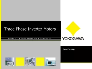
This paper concentrates on modeling and simulation of single phase inverter as a frequency changer modulated by sinusoidal Pulse Width Modulation PWM technique. An inverter is a circuit that converts DC sources to AC sources. To judge the quality of voltage produced by a PWM inverter, a detailed harmonic analysis of the voltage waveform is done. Pulse width modulated PWM inverters are among the most used power electronic circuits in practical applications. These inverters are capable of producing ac voltages of variable magnitude as well as variable frequency with less harmonic distortion. The model is executed utilizing MATLAB Simulink software with the SimPower System Block Set using PC simulation. MATLAB Simulink is a successful instrument to examine a PWM inverter. Major reasons for using MATLAB are Faster reaction, accessibility of different simulation devices and the nonappearance of joining issues. In this paper, Insulated Gate Bipolar Transistor IGBT is used as switching power device. IGBT is ideal since it high switching speed and also high input impedance. Finally a MATLAB SIMULINK model for the SPWM is presented. Various simulation results are also included. Asha Durafe "Matlab/Simulink Model of Sinusoidal PWM For Three-Phase Voltage Source Inverter" Published in International Journal of Trend in Scientific Research and Development (ijtsrd), ISSN: 2456-6470, Volume-2 | Issue-6 , October 2018, URL: https://www.ijtsrd.com/papers/ijtsrd18614.pdf Paper URL: http://www.ijtsrd.com/engineering/electrical-engineering/18614/matlabsimulink-model-of-sinusoidal-pwm-for-three-phase-voltage-source-inverter/asha-durafe<br>

E N D
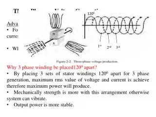
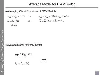
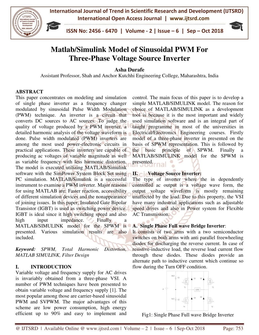
International Journal of Trend in International Open Access Journal International Open Access Journal | www.ijtsrd.com International Journal of Trend in Scientific Research and Development (IJTSRD) Research and Development (IJTSRD) www.ijtsrd.com ISSN No: 2456 ISSN No: 2456 - 6470 | Volume - 2 | Issue – 6 | Sep 6 | Sep – Oct 2018 Matlab/Simulink Mo Three-Phase Simulink Model of Sinusoidal PWM Phase Voltage Source Inverter Asha Durafe nd Anchor Kutchhi Engineering College,Maharashtra Sinusoidal PWM For Assistant Professor,Shah and Maharashtra, India ABSTRACT This paper concentrates on modeling and simulation of single phase inverter as a frequency changer modulated by sinusoidal Pulse Width Modulation (PWM) technique. An inverter is a circuit that converts DC sources to AC sources. To judge the quality of voltage produced by a PWM inverter, a detailed harmonic analysis of the voltage waveform is done. Pulse width modulated (PWM) inverters are among the most used power-electronic circuits in practical applications. These inverters are capable of producing ac voltages of variable magnitude as well as variable frequency with less harmonic distortion. The model is executed utilizing MATLAB/Simulink software with the SimPower System Block Set using PC simulation. MATLAB/Simulink is a successful instrument to examine a PWM inverter. Major reasons for using MATLAB are: Faster reaction, accessibility of different simulation devices and the nonappearance of joining issues. In this paper, Insulated Gate Bipolar Transistor (IGBT) is used as switching power device. IGBT is ideal since it high switching speed and also high input impedance. MATLAB/SIMULINK model for the SPWM is presented. Various simulation results are also included. Keyword: SPWM, Total Harmonic Distortion, MATLAB SIMULINK, Filter Design I. INTRODUCTION Variable voltage and frequency supply for AC drives is invariably obtained from a three-phase VSI. A number of PWM techniques have been presented to obtain variable voltage and frequency supply [1]. The most popular among those are carrier-based sinusoidal PWM and SVPWM. The major advantages of this scheme are low power consumption, high energy efficient up to 90% and easy to implement and efficient up to 90% and easy to implement and control. The main focus of this paper is to develop a simple MATLAB/SIMULINK model. The reason for choice of MATLAB/SIMULINK as a development tool is because it is the most important and widely used simulation software and is an integral part of taught programme in most of the universities in Electrical/Electronics Engineering courses. Firstly model of a three-phase inverter in presented on the basis of SPWM representation. This is followed by the basic principle of MATLAB/SIMULINK model for the SPWM is presented. II. Voltage Source Inverter: The type of inverter where the in controlled ac output is a voltage wave output voltage waveform is mostly remaining unaffected by the load. Due to this property, the VSI have many industrial applications such as adjustable speed drives and also in Power system for Flexible AC Transmission. A. Single Phase Full wave Bridge Inverter It consists of two arms with a two semiconductor switches on both arms with anti diodes for discharging the reverse current. In case of resistive-inductive load, the reverse load current fl through these diodes. These diodes provide an alternate path to inductive current which continue so flow during the Turn OFF condition. flow during the Turn OFF condition. concentrates on modeling and simulation of single phase inverter as a frequency changer modulated by sinusoidal Pulse Width Modulation (PWM) technique. An inverter is a circuit that converts DC sources to AC sources. To judge the control. The main focus of this paper is to develop a simple MATLAB/SIMULINK model. The reason for IMULINK as a development tool is because it is the most important and widely used simulation software and is an integral part of taught programme in most of the universities in Electrical/Electronics Engineering courses. Firstly d by a PWM inverter, a detailed harmonic analysis of the voltage waveform is done. Pulse width modulated (PWM) inverters are rter in presented on the electronic circuits in basis of SPWM representation. This is followed by the basic principle of MATLAB/SIMULINK model for the SPWM is practical applications. These inverters are capable of SPWM. SPWM. Finally Finally a a riable magnitude as well as variable frequency with less harmonic distortion. The model is executed utilizing MATLAB/Simulink software with the SimPower System Block Set using PC simulation. MATLAB/Simulink is a successful Voltage Source Inverter: The type of inverter where the in dependently is a voltage wave form, the output voltage waveform is mostly remaining unaffected by the load. Due to this property, the VSI have many industrial applications such as adjustable speed drives and also in Power system for Flexible ter. Major reasons for using MATLAB are: Faster reaction, accessibility of different simulation devices and the nonappearance of joining issues. In this paper, Insulated Gate Bipolar Transistor (IGBT) is used as switching power device. it high switching speed and also high input impedance. MATLAB/SIMULINK model for the SPWM is presented. Various simulation results are also Finally Finally a a Single Phase Full wave Bridge Inverter: It consists of two arms with a two semiconductor switches on both arms with anti parallel freewheeling diodes for discharging the reverse current. In case of inductive load, the reverse load current flow through these diodes. These diodes provide an alternate path to inductive current which continue so SPWM, Total Harmonic Distortion, Variable voltage and frequency supply for AC drives phase VSI. A number of PWM techniques have been presented to obtain variable voltage and frequency supply [1]. The based sinusoidal PWM and SVPWM. The major advantages of this scheme are low power consumption, high energy Fig1: Single Phase Full wave Bridge Inverter Fig1: Single Phase Full wave Bridge Inverter @ IJTSRD | Available Online @ www.ijtsrd.com www.ijtsrd.com | Volume – 2 | Issue – 6 | Sep-Oct 2018 Oct 2018 Page: 753
International Journal of Trend in Scientific Research and Development (IJTSRD) ISSN: 2456 International Journal of Trend in Scientific Research and Development (IJTSRD) ISSN: 2456 International Journal of Trend in Scientific Research and Development (IJTSRD) ISSN: 2456-6470 Sinusoidal pulse width modulation technique is adopted in order to reduce the harmonic content of output voltage and to obtain an electrical near Sinusoidal pulse width modulation technique is adopted in order to reduce the harmonic content of output voltage and to obtain an electrical near sinusoidal output voltage. III. Harmonics: Harmonics are brought on by non are loads that draw a non-sinusoidal current from a sinusoidal voltage source. Some cases of harmonic creating loads are ?Electric circular segment heaters ?Static VAR compensators ?Inverters ?DC converters ?Switch Mode Power Supplies and AC or DC engine drives This paper describes the Harmonic examination of Single Phase inverter with Pulse Width Modulation (PWM). The Simulink demonstrate for both straightforward and down to earth inverter has been designed in MATLAB. IV. Simulation Results: Simulation model have implemented using MATLAB SIMULINK tool. The proposed Simulink model has been shown in figure 2 and figure 3 in which modeling and simulation of single phase inverter as a frequenc modulated by Pulse Width Modulation (PWM) has been designed. Load voltage, load current have been shown in figure 4. The PWM generation is shown in figure 5 and the Harmonic profile with THD value is shown in figure 6. The different parameters of inverter, for example, R, C and Filter plane are shifted and the subsequent voltage and current diagrams has been examined. Harmonics are brought on by non-straight loads that sinusoidal current from a sinusoidal voltage source. Some cases of harmonic Electric circular segment heaters Table 1: Switching States Table 1: Switching States The switches are T1, T2, T3 and T4. The switches in each branch is operated alternatively so that they are not in same mode (ON /OFF) simultaneously .In practice they are both OFF for short period called blanking time, to avoid short circuiting. switches T1 and T2 or T3 and T4 should operate in a pair to get the output. These bridges legs are switched such that the output voltage is shifted from one to another and hence the change in polarity occurs in voltage waveform. If the shift angle is zer voltage is also zero and maximal when shift angle is π. B. SPWM (Sinusoidal Pulse Width Modulation Technique): This type of modulation is implemented by comparing a sinusoidal modulating signal Vm (ωt) = Vm sin with a triangular carrier signal of maximum height Vc [8]. The natural intersection of Vm (ωt) and Vc determine both the onset and duration of the modulated pulses. PWM gives an approach to diminish the Total Harmonic Distortion (THD) of load current. The THD prerequisite can b more effortlessly when the yield of PWM inverter is separating. The unfiltered PWM yield will have a generally high THD, yet the harmonic will be at the much higher frequencies than for a square wave, making sifting effectively. The aggregate distortion, or THD, is characterized as the proportion of the total of the powers of every single harmonic segment to the power of the central. Control of the switches for the sinusoidal PWM yield requires a reference flag (tweaking or control flag) which is a sinusoidal wave and a bearer flag which a triangular wave that control the exchanging frequency. There two kind of the exchanging for PWM, unipolar exchanging and bipolar exchanging. In a unipolar exchanging plan for PWM, the yield is change either high. The switches are T1, T2, T3 and T4. The switches in each branch is operated alternatively so that they are not in same mode (ON /OFF) simultaneously .In Switch Mode Power Supplies and AC or DC short period of time circuiting. The This paper describes the Harmonic examination of Single Phase inverter with Pulse Width Modulation (PWM). The Simulink demonstrate for both straightforward and down to earth inverter has been switches T1 and T2 or T3 and T4 should operate in a pair to get the output. These bridges legs are switched such that the output voltage is shifted from one to another and hence the change in polarity occurs in voltage waveform. If the shift angle is zero, the output voltage is also zero and maximal when shift angle is Simulation implemented using MATLAB SIMULINK tool. The proposed Simulink model has been shown in figure 2 and figure 3 in which modeling and simulation of single phase inverter as a frequency changer modulated by Pulse Width Modulation (PWM) has been designed. Load voltage, load current have been shown in figure 4. The PWM generation is shown in figure 5 and the Harmonic profile with THD value is shown in figure 6. The different parameters of the inverter, for example, R, C and Filter plane are shifted and the subsequent voltage and current diagrams has model have been been designed designed and and SPWM (Sinusoidal Pulse Width Modulation This type of modulation is implemented by comparing ωt) = Vm sinωt ignal of maximum height Vc ωt) and Vc (ωt) determine both the onset and duration of the modulated pulses. PWM gives an approach to diminish the Total Harmonic Distortion (THD) of load current. The THD prerequisite can be met all the more effortlessly when the yield of PWM inverter is separating. The unfiltered PWM yield will have a generally high THD, yet the harmonic will be at the much higher frequencies than for a square wave, making sifting effectively. The aggregate harmonic distortion, or THD, is characterized as the proportion of the total of the powers of every single harmonic segment to the power of the central. Control of the switches for the sinusoidal PWM yield requires a ag) which is a sinusoidal wave and a bearer flag which a triangular wave that control the exchanging frequency. There two kind of the exchanging for PWM, unipolar exchanging and bipolar exchanging. In a unipolar exchanging plan for PWM, the yield is changed from Figure 2: Single phase SPWM Inverter Figure 2: Single phase SPWM Inverter @ IJTSRD | Available Online @ www.ijtsrd.com www.ijtsrd.com | Volume – 2 | Issue – 6 | Sep-Oct 2018 Oct 2018 Page: 754
International Journal of Trend in Scientific Research and Development (IJTSRD) ISSN: 2456 International Journal of Trend in Scientific Research and Development (IJTSRD) ISSN: 2456 International Journal of Trend in Scientific Research and Development (IJTSRD) ISSN: 2456-6470 V. This paper describes the Harmonic analysis of Single Phase inverter with Pulse Width Modulation (PWM). It includes both practical inverter generator circuit. The Simulink models for both the circuits have been MATLAB/SIMULINK. Its various parameters such as R, L load and filter design components are varied and the resulting voltage and current graphs have been studied. VI. References: 1.Kim. J, Choi. J & Hong. H, "Output LC Filter Design of Voltage Source Inverter Considering the Performance of Controller" IEEE Conference Publications, 2000. 2.Lin. W. Song & Huang. Reduction in Inverters by Use of Width Modulation” IEEE Transactions on Industrial Electronics - ELECTRON , vol. IECI- 1980 3.Gole. A. M “Harmonic Elimination in SPWM Inverter"1994, Halifax, Canada. 4.Ming Li, Dong Dai & Xikui Ma, "Slow Fast-Scale Instabilities Controlled Full-Bridge Inverter" Journal: Circuits Systems and Signal Processing SIGNAL PROCESS , vol. 27, no. 6, pp. 811 2008. 5.Maswood. Ali. I & Al-Ammar. Essam "Analysis of a PWM Voltage Source Inverter with PI Controller under International Power Engineering Conference IPEC, 2010. 6.Anand. D & Jeevananthan .S "Modeling and Analysis of Conducted EMI Emissions of a Single-Phase PWM Inverters" Asian Power Electronics Journal, Vol. 4, No.3 December 2010. 7.Crowley. Ian. F & Leung. H. F "PWM Techniques: A Pure Sine Wave Inverter" Worcester Polytechnic Institute Major Qualifying Project, 2010. 8.J.M.D. Murphy and F.G. Turnbull, Power Electronic Control of AC motors, Perg 1988. 9.M. H. Rashid, Power Electronics, Prentice 1998. 10.Ned Mohan, M.Undeland and P.Robbins, Power Electronics, John Wiley & Sons, 1995. Electronics, John Wiley & Sons, 1995. Conclusion: This paper describes the Harmonic analysis of Single Phase inverter with Pulse Width Modulation (PWM). It includes both practical inverter circuit and PWM generator circuit. The Simulink models for both the circuits have been MATLAB/SIMULINK. Its various parameters such as R, L load and filter design components are varied and the resulting voltage and current graphs have been simulated simulated in in Figure 3: SPWM Generator Figure 3: SPWM Generator Kim. J, Choi. J & Hong. H, "Output LC Filter Design of Voltage Source Inverter Considering the Performance of Controller" IEEE Conference Song & Huang. I. Bau “Harmonic Reduction in Inverters by Use of Sinusoidal Pulse Width Modulation” IEEE Transactions on IEEE TRANS IND -27, no. 3, pp. 201-207, M “Harmonic Elimination in SPWM Inverter"1994, Halifax, Canada. Ming Li, Dong Dai & Xikui Ma, "Slow-Scale and Scale Instabilities Bridge Inverter" Journal: Circuits Systems and Signal Processing - CIRC SYST SIGNAL PROCESS , vol. 27, no. 6, pp. 811-831, Figure 4: SPWM Waveform Figure 4: SPWM Waveform in in Voltage Voltage- Mode Ammar. Essam "Analysis age Source Inverter with PI under Power Engineering Conference- Controller Non Non-ideal conditions” Figure 5: Load voltage and load current Anand. D & Jeevananthan .S "Modeling and Analysis of Conducted EMI Emissions of a Phase PWM Inverters" Asian Power ics Journal, Vol. 4, No.3 December 2010. Crowley. Ian. F & Leung. H. F "PWM Techniques: A Pure Sine Wave Inverter" Worcester Polytechnic Institute Major Qualifying J.M.D. Murphy and F.G. Turnbull, Power Electronic Control of AC motors, Pergamon Press, M. H. Rashid, Power Electronics, Prentice-Hall, Ned Mohan, M.Undeland and P.Robbins, Power Figure 6: THD of Output Voltage Waveform for Single Pulse Width Modulated Inverter Single Pulse Width Modulated Inverter THD of Output Voltage Waveform for @ IJTSRD | Available Online @ www.ijtsrd.com www.ijtsrd.com | Volume – 2 | Issue – 6 | Sep-Oct 2018 Oct 2018 Page: 755