Download
1 / 28
290 likes | 307 Views
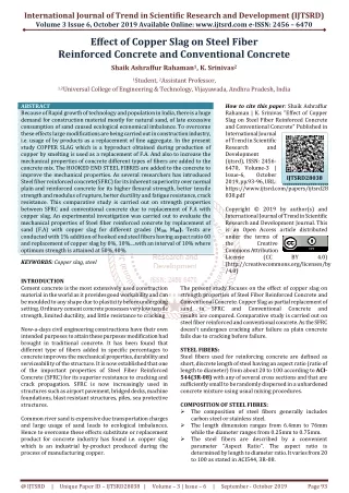
Cement concrete is the most extensively used construction material in the world. The reason for its extensive use is that it provides good workability and can be moulded to any shape. Ordinary cement concrete possesses a very low tensile strength, limited ductility and little resistance to cracking, internal micro cracks, leading to brittle failure of concrete. In this modern age, civil engineering constructions have their own structural and durability requirements, every structure has its own intended purpose and hence to meet this purpose, modification in traditional cement concrete has become mandatory. It has been found that different type of fibers added in specific percentage to concrete improves the mechanical properties, durability and serviceability of the structure. It is now established that one of the important properties of Steel Fiber Reinforced Concrete SFRC is its superior resistance to cracking and crack propagation. In this study the effect of Steel fibers on early strength of concrete have been studied by varying the percentage of fibers in concrete. The Chemical admixture used in the concrete is CaCl2 Accelerator .Fibre content were varied by 0 , 0.50 , 0.75 , 1 , 1.5 and 2 by volume of concrete. Cubes of size 150mmX150mmX150mm to check the compressive strength, Cylinders of size 100mmx200m to check the split tensile strength and beams of size 500mmX100mmX100mm for checking flexural strength were casted. All the specimens were cured for the period of 3, 7 and 28 days before crushing. The results of Steel fiber reinforced concrete on early strength for 3days, 7days and 28days curing with varied percentage of fiber were studied and it has been found that there is significant strength improvement in Early Strength concrete. The optimum fiber content while studying the compressive strength, Split tensile strength and flexural strength is found to be 1.25 . Also, it has been observed that with the increase in fiber content up to the optimum value, the concrete gains maximum compressive strength at 28 days curing while split tensile and flexural performance shows maximum percentage increase in strength in first 3 days of curing. Slump cone test was adopted to measure the workability of concrete. The Slump cone test results revealed that workability gets reduced with the increase in fiber content. Kamran Mohi Ud Din Bhat | Mohd Zeeshan Khan "Effect of Steel Fibre Reinforcement on Early Strength of Concrete" Published in International Journal of Trend in Scientific Research and Development (ijtsrd), ISSN: 2456-6470, Volume-2 | Issue-5 , August 2018, URL: https://www.ijtsrd.com/papers/ijtsrd15781.pdf Paper URL: http://www.ijtsrd.com/engineering/civil-engineering/15781/effect-of-steel-fibre-reinforcement-on-early-strength-of-concrete/kamran-mohi-ud-din-bhat<br>

E N D
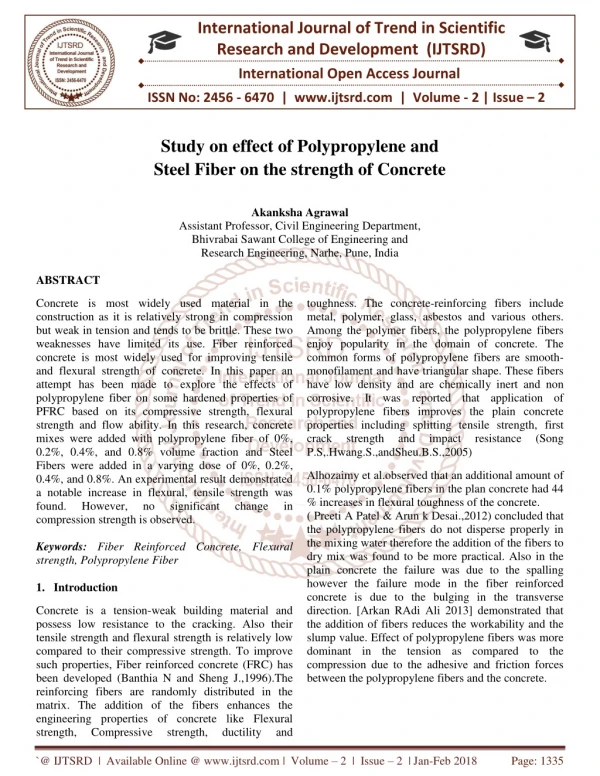
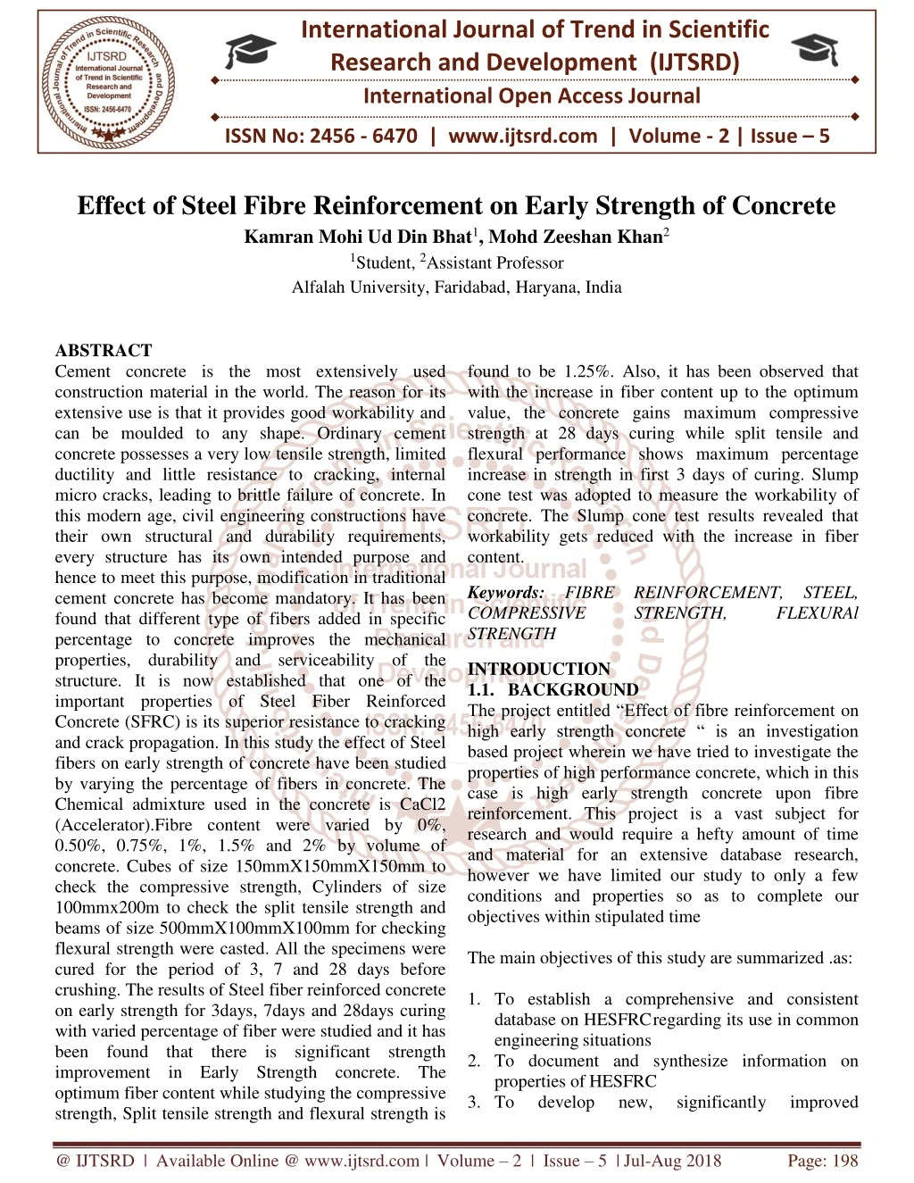
International Journal of Trend in Scientific Research and Development (IJTSRD) International Open Access Journal ISSN No: 2456 - 6470 | www.ijtsrd.com | Volume - 2 | Issue – 5 Effect of Steel Fibre Reinforcement on Early Strength of Concrete Kamran Mohi Ud Din Bhat1, Mohd Zeeshan Khan2 1Student, 2Assistant Professor Alfalah University, Faridabad,Haryana, India ABSTRACT Cement concrete is the most extensively used construction material in the world. The reason for its extensive use is that it provides good workability and can be moulded to any shape. Ordinary cement concrete possesses a very low tensile strength, limited ductility and little resistance to cracking, internal micro cracks, leading to brittle failure of concrete. In this modern age, civil engineering constructions have their own structural and durability requirements, every structure has its own intended purpose and hence to meet this purpose, modification in traditional cement concrete has become mandatory. It has been found that different type of fibers added in specific percentage to concrete improves the mechanical properties, durability and serviceability of the structure. It is now established that one of the important properties of Steel Fiber Reinforced Concrete (SFRC) is its superior resistance to cracking and crack propagation. In this study the effect of Steel fibers on early strength of concrete have been studied by varying the percentage of fibers in concrete. The Chemical admixture used in the concrete is CaCl2 (Accelerator).Fibre content were varied by 0%, 0.50%, 0.75%, 1%, 1.5% and 2% by volume of concrete. Cubes of size 150mmX150mmX150mm to check the compressive strength, Cylinders of size 100mmx200m to check the split tensile strength and beams of size 500mmX100mmX100mm for checking flexural strength were casted. All the specimens were cured for the period of 3, 7 and 28 days before crushing. The results of Steel fiber reinforced concrete on early strength for 3days, 7days and 28days curing with varied percentage of fiber were studied and it has been found that there is significant strength improvement in Early Strength concrete. The optimum fiber content while studying the compressive strength, Split tensile strength and flexural strength is found to be 1.25%. Also, it has been observed that with the increase in fiber content up to the optimum value, the concrete gains maximum compressive strength at 28 days curing while split tensile and flexural performance shows maximum percentage increase in strength in first 3 days of curing. Slump cone test was adopted to measure the workability of concrete. The Slump cone test results revealed that workability gets reduced with the increase in fiber content. Keywords: FIBRE REINFORCEMENT, STEEL, COMPRESSIVE STRENGTH, STRENGTH FLEXURAl INTRODUCTION 1.1. BACKGROUND The project entitled “Effect of fibre reinforcement on high early strength concrete “ is an investigation based project wherein we have tried to investigate the properties of high performance concrete, which in this case is high early strength concrete upon fibre reinforcement. This project is a vast subject for research and would require a hefty amount of time and material for an extensive database research, however we have limited our study to only a few conditions and properties so as to complete our objectives within stipulated time The main objectives of this study are summarized .as: 1.To establish a comprehensive and consistent database on HESFRC regarding its use in common engineering situations 2.To document and synthesize information on properties of HESFRC 3.To develop new, significantly improved @ IJTSRD | Available Online @ www.ijtsrd.com | Volume – 2 | Issue – 5 | Jul-Aug 2018 Page: 198
International Journal of Trend in Scientific Research and Development (IJTSRD) ISSN: 2456-6470 engineering criteria for behavior and mechanical properties of HESFRC 4.To develop some guidelines and practical recommendations for HESFRC according to intended use and suitability. Although a number of investigations have been dealt with Fibre Reinforced and High performance concrete before however we don’t have much literature on fibre reinforcement of high early strength concrete. The main intent will be to achieve, besides minimum compressive strength, a post cracking strength in bending higher than the cracking strength so as to minimize crack widths and also ensure a higher resistance to repeated loads after cracking. Particular attention will be given to recording key parameters such as compressive strength, tensile strength, flexural strength and their variation with different percentages of fibre addition. OBJECTIVES The main objectives of this investigation will be 1.To establish a consistent and comprehensive database on the properties of high early strength fibre reinforced concrete (HESFRC) 2.To document and synthesize information on the properties of the fresh mix and the mechanical properties of the hardened composite, and 3.To develop some practical recommendations for use of HESFRC by the profession. The experimental investigation included several parts dealing with the properties of HESFRC: the properties of the fresh mix (workability by the slump test and unit weight), and the compressive and tensile, properties of the hardened composite. Only HESFRC will be considered which has been already defined as achieving a minimum target compressive strength of 35 MPa in 24 hours In relation to the part of the experimental program dealing with the compression tests, following goals will be undertaken: 1.To measure the fresh properties of various HESFRC mixes, which include plastic unit weight, workability (using the cone test) 2.To determine the values of strength and modulus of elasticity of the composite and their variation with time between 1 day and 28 days. As far as current application of FRC is concerned, a low %age of fibres (0.01-1.0 %) is being used. In this study, we will try higher %ages of fibres (up to 2%) SCOPE High early strength concrete, when reinforced with fibres, can be used for several highway related applications. They include repair-type applications for which early strength properties are needed such as for potholes, bridge decks, overlays, pavement joints, and runways; and applications in new structures particularly bridge decks, pavements, median barriers, taxiways, and runways. Tunnel lining, slope stabilisation, dams, hydraulic structures, and blast resistant structures also utilize high early strength fibre reinforced concrete for various purposes. These are applications in which the specific advantages of HESFRC compared with HES concrete without fibres are needed, such as its increased resistance to cracking, its increased toughness (i.e., energy absorption capacity against dynamic and impact loadings), its increased ductility, and its increased fatigue life. Moreover, HESFRC can be used in reinforced and prestressed concrete structures to replace the plain concrete matrix in these structures. In such cases, its use is expected to lead to substantially improved structural ductility, better hysteretic response under cyclic load reversals, better bonding of the reinforcing bars and prestressing tendons, improved resistance of the concrete cover to spalling, smaller crack widths, and overall improved energy absorption capacity of the structure. METHODOLOGY The procedure involved in our project work is summarized as: 1.Collection and testing of materials The materials were collected from the university construction sites and stored in the laboratory and the necessary tests were carried out. Fineness test and initial setting time of OPC and OPC with admixture was carried out. Sieve analysis of fine aggregates was done. For coarse aggregates, flakiness index, elongation index, abrasion, AIV, aggregate crushing value was done. The steel fibres needed to be cut to required size. The chemical was also powdered before use. professional use of @ IJTSRD | Available Online @ www.ijtsrd.com | Volume – 2 | Issue – 5 | Jul-Aug 2018 Page: 199
International Journal of Trend in Scientific Research and Development (IJTSRD) ISSN: 2456-6470 2.Concreting Concrete was formed at different percentages of fibres, which varied as 0%, 0.5%, 0.75%, 1.0%, 1.25%, 1.5% and 2.0% Concreting was done by design mix procedure. Atmospheric conditions were moderate temperature with average humidity. After concreting, workability tests of all samples were carried out. 3.Casting of cubes, cylinders and beams After concreting was done, concrete was poured into cube, cylinder, and beam moulds. The moulds were compacted after that and left as such for 24 hours. Curing was done by placing the specimen in curing tank till 6 hours before testing. 4.Testing of samples Samples were tested for various loadings. Cubes were put to compression, beams to two point loading for flexure and cylinders were subjected to split tensile strength. Each test was carried out on 3 samples and the arithmetic average was taken as the mean value. Quality control was maintained throughout the project. All the steps were carried out as per Indian standards enlisted below: 1.IS 456:2000 concrete design 2.Is 10262:2009 concrete mix proportions 3.Is 4031:1988 part iv Guidelines for method of test of aggregate 4.Is 4031:1988 part v- Guidelines for method of test of aggregate 5.Is 12269:1988- grade cement 6.Is 383:1970 coarse and fine aggregates 7.Is 4926:2003 ready mix concrete Code of practice for Guidelines for Specifications for 53 Specifications for Code of practice for STRUCTURE OF PROJECT @ IJTSRD | Available Online @ www.ijtsrd.com | Volume – 2 | Issue – 5 | Jul-Aug 2018 Page: 200
International Journal of Trend in Scientific Research and Development (IJTSRD) ISSN: 2456-6470 A. Cement Although all the materials that go into concrete are essential but by far cement is the most important constituent because it is the most delicate link of the chain. The main function of the cement is to bind sand and coarse aggregates to form a compact mass. ➢Composition of cement Cement comprises of compounds of calcium, silicon, aluminum, iron, and oxygen. The main function of cement is to bind the aggregates and to fill the voids in between the aggregates. The most commonly used cement is the Ordinary Portland Cement (OPC). It is obtained by burning together, in a definite proportion, a mixture of naturally occurring argillaceous and calcareous material to a partial fusion at high temperature (1450 °C). The composition of OPC is rather complicated but basically it comprises of four main compounds LITERATURE REVIEW CONCRETE Concrete is the most widely used manmade construction material used on earth and is only second to water as the most utilized substance on the planet. a composite mixture obtained by mixing cement, water and an inert matrix of sand and gravel or crushed stone, and when placed in forms, allowed to cure, hardens into a rock like mass known as cement concrete. The strength, durability and other properties of concrete depend on properties of its ingredients, on proportion mix, the method of compaction and other controls during placing, compaction, and curing. INGREDIENTS OF CONCRETE Concrete consists of two types of ingredients viz Active and Inactive. Active group consists of cement and water whereas inactive group consists of fine and coarse aggregates. The in active group isalso sometimes called as inert matrix. These ingredients are discussed as: • 3CaO.SiO2 (alite) 25-50% Tricalcium silicate (C3S), • 2CaO.SiO2(belite) 20-40% Dicalcium silicate(C2S) , • 3cao.al2o3 (aluminate) 5-12% Tricalcium aluminate(C3A), • 4CaO.Al2O3.Fe2O3(ferrite) 6-12% Tetracalcium alumino ferrite(C4AF) Differences in various types of ordinary Portland cements arise due to variations in relative proportions of these compounds in cement. B. Aggregates Aggregates are divided into two categories on the basis of size 1.Coarse aggregates (size greater than 4.75mm). 2.Finer aggregates (less or equal to 4.75mm). Aggregate consists of large chunks of material in a concrete mix. Almost all natural aggregate material originate from bed rocks. Size of aggregates varies perhaps 80mm is maximum size that could be conveniently used. The shape of aggregates may be round, irregular or partly round or angular, flaky. The shape of aggregates greatly affects the workability. C. Water Combining water with a cementations material forms a cement paste by the process of hydration. The cement paste glues the aggregate together, fills voids within it, and makes it flow more freely. A lower water-to-cement ratio yields a stronger, more durable concrete, whereas more water gives a freer-flowing concrete with a higher slump. Impure water used to make concrete can cause problems when setting or in causing premature failure of the structure. Hydration involves many different reactions, often occurring at the same time. As the reactions proceed, the products of the cement hydration process gradually bond together the individual sand and gravel particles and other components of the concrete to form a solid mass. D. Admixture Chemical admixtures are materials in the form of powder or fluids that are added to the concrete to give it certain characteristics not obtainable with plain concrete mixes. Accelerators speed up the hydration (hardening) of the concrete. Typical materials used are CaCl2, Ca(NO3)2 and admixtures are especially useful for modifying the NaNO3. Accelerating @ IJTSRD | Available Online @ www.ijtsrd.com | Volume – 2 | Issue – 5 | Jul-Aug 2018 Page: 201
International Journal of Trend in Scientific Research and Development (IJTSRD) ISSN: 2456-6470 properties of concrete in cold weather. While as retarders slow the hydration of concrete and are used in large or difficult pours where partial setting before the pour is complete is undesirable. Typical polyol retarders are sugar, sucrose, sodium gluconate, glucose, citric acid, and tartaric acid. Plasticizers increase the workability of plastic or "fresh" concrete, allowing it be placed more easily, with less consolidating effort. A typical plasticizer is lingo-sulfonate. Plasticizers can be used to reduce the water content of a concrete while maintaining workability and are sometimes called water-reducers due to this use. Such treatment improves its strength and durability characteristics HIGH PERFORMANCE CONCRETE (HPC) In recent years, improvements in properties of concrete have been achieved in the so called High performance concrete by improvements involving a combination of improved compaction, improved paste characteristics and aggregate-matrix bond and reduced porosity. Subsequent reduction in water cement ratio is achieved through use of plasticisers. Although HPCs are made from same materials as normal concrete but they are considered quite different materials due to their higher qualitative and quantitative performances. They offer different advantages such as enhanced durability, reduced permeability, higher strength, early setting etc. Based on characteristic strength, a concrete can be called as HPC if it produces a strength of 600- 100 Mpa in 28 days (compared to 10-20 of ordinary concrete). Fibre reinforcing concretes are becoming quite a common today due to accessory advantages besides increase in strength and reduction in cost. High early strength is a common HPC used mainly in underground construction, repair works, construction on busy routes etc. There are three methods which make adjustments to obtain high-early strength in concrete: 1.Adding 30% more cement by weight to the normal cement content (the fine aggregate is reduced) while the water and air contents remain unchanged. 2.Adding chemical admixtures to the standard mix. 3.A combination of 1 and 2. The additional 30% cement or addition of a water reducer increases the cement-voids ratio of the mix and thereby strength is increased. Accelerating admixtures added to a standard mix, without changing the cement or water content, increase the rate of hydration thereby increasing the early strength but reducing the ultimate strength. Increasing the cement content 30% produces high- early strength concrete. Do not increase the water content more than 5% over that used with the normal cement content. There is a tendency to increase the water content to the extent that the same slump is obtained. The addition of excess water will nullify the benefits of the increased cement content and produce a lower early and lower ultimate strength than anticipated. The actual slump value is less in a higher cement content mix due to the increased workability of the mixture that is a result of the high cement content. The lower slump concrete with the additional cement is just as workable as the normal concrete FIBRE REINFORCED CONCRETE Concrete is the most widely used man-made construction material in the world, and is second only to water as the most utilized substance on the planet. It is obtained by mixing cementing materials, water and aggregates, and sometimes admixtures, in required proportions. The mixture when placed in forms and allowed to cure hardens into a rock-like mass known as concrete. The strength, durability and other characteristics of concrete depend upon the properties of its ingredients, on the proportions of mix, the method of compaction and other controls during placing, compaction, and curing. Concrete is weak in tension and has a brittle character. The concept of using fibres to improve the characteristics of construction materials is very old. Early applications include addition of straw to mud bricks, horse hair to reinforce plaster and asbestos to reinforce pottery. Use of continuous reinforcement in concrete (reinforced concrete) increases strength and ductility, but requires careful placement and labour skill. Alternatively, introduction of fibres in discrete form in plain or reinforced concrete may provide a better solution. The modern development of fibre reinforced concrete (FRC) started in the early sixties. Addition of fibres to concrete makes it a homogeneous and isotropic material. When concrete cracks, the randomly oriented fibres start functioning, arrest crack formation and propagation, and thus improve strength and ductility. The failure modes of FRC are either bond failure between fibre and matrix or material failure. @ IJTSRD | Available Online @ www.ijtsrd.com | Volume – 2 | Issue – 5 | Jul-Aug 2018 Page: 202
International Journal of Trend in Scientific Research and Development (IJTSRD) ISSN: 2456-6470 Fibres are produced from different materials in various shapes and sizes. Typical fibre materials are: ➢Steel Fibres Straight, crimped, twisted, hooked, ringed, and paddled ends. Diameter range from 0.25 to 0.76mm. ➢Glass Fibres Straight. Diameter ranges from 0.005 to 0.015mm (may be bonded together to form elements with diameters of 0.13 to 1.3mm). ➢Natural Organic and Mineral Fibres Wood, asbestos, cotton, bamboo, and rock-wool. They come in wide range of sizes. ➢Polypropylene Fibres Plain, twisted, fibrillated, and with buttoned ends. ➢Other Synthetic Fibres Kevlar, nylon, and polyester. Diameter ranges from 0.02 to 0.38mm. A convenient parameter describing a fibre is its aspect ratio (LID), defined as the fibre length divided by an equivalent fibre diameter. Typical aspect ratio ranges from about 30 to 150 for length of 6 to 75mm. A shortcoming of using fibres in concrete is reduction in workability. Workability of FRC is affected by fibre aspect ratio and volume fraction as well the workability of plain concrete. As fibre content increases, workability decreases. Most researchers limit volume of fibres to 4.0% and aspect ratio to 100 to avoid unworkable mixes. In addition, some researchers have limited the fibre reinforcement index [volume of fibres as % ×aspect ratio] to 1.5 for the same reason. To overcome the workability problems associated with FRC, modification of concrete mix design is recommended. Such modifications can include the use of additives. HISTORY The use of fibers to increase the structural properties of construction material is not a new process. From ancient times fibers were being used in construction. In BC, horse hair was used to reinforce mortar. Egyptians used straw in mud bricks to provide additional strength. Asbestos was used in the concrete in the early 19th century, to protect it from formation of cracks. But in the late 19th century, due to increased structural importance, introduction of steel reinforcement in concrete was made, by which the concept of fiber reinforced concrete was over looked for 5-6 decades. Later in 1939 the introduction steel replacing asbestos was made for the first time. But at that period it was not successful. From 1960, there was a tremendous development in the FRC, mainly by the introduction of steel fibers. Since then use of different types of fibers in concrete was made. In 1970’s principles were developed on the working of the fibres reinforced concrete. Later in 1980’s certified process was developed for the use of FRC. In the last decades, codes regarding the FRC are being developed. PROPERTIES OF FIBRE CONCRETE Properties of concrete is affected by many factors like properties of cement, fine aggregate, coarse aggregate. Other than this, the fibre reinforced concrete is affected by following factors: ➢Type of fibre ➢Aspect ratio ➢Quantity of fibre ➢Orientation of fibre Type of fibre: A good fibre is the one which possess the following qualities: ➢Good adhesion within the matrix. Adaptable elasticity modulus (sometimes higher than that of the matrix) REINFORCED ➢Compatibility with the binder, which should not be attacked or destroyed in the long term ➢An accessible price, taking into account the proportion within the mix being sufficiently short, fine and flexible to permit mixing, transporting and placing ➢Being sufficiently strong, yet adequately robust to withstand the mixing process. Aspect ratio: Aspect ratio is defined as the ratio of length to width of the fibre. The value of aspect ratio varies from 30 to 150. Generally the increase in aspect ratio increases the strength and toughness till the aspect ratio of 100. Above that the strength of concrete decreases, in view of decreased workability and reduced compaction. From investigations it can be found out that good results are obtained at an aspect ratio around 80 for steel fibres. Keeping that in view we have considered @ IJTSRD | Available Online @ www.ijtsrd.com | Volume – 2 | Issue – 5 | Jul-Aug 2018 Page: 203
International Journal of Trend in Scientific Research and Development (IJTSRD) ISSN: 2456-6470 steel crimped fibres with aspect ratio of 50-80 (Length 40-50 mm and Diameter 0.75 mm). Fibre quantity: Generally quantity of fibres is measured as percentage of cement content or concrete. As the volume of fibres increase, there should be increase in strength and toughness of concrete. Regarding our fibre, we hope that there will be an increase in strength, with increase in fibre content. We are going to test for percentages of 0, 0.5, 0.75, 1.0, 1.25, 1.5, and 2.0 % volume of concrete Orientation of fibre: The orientations of fibres play a key role in determining the capacity of concrete. In RCC the reinforcements are placed in desired direction. But in FRC, the fibres will be oriented in random direction. The FRC will have maximum resistance when fibres are oriented parallel to the load applied. The stress strain curve of concrete under uniaxial compression shows a linear behaviour up to about 30% of the ultimate strength (fu) because under short term loading the micro cracks in the transition zone remain undisturbed. For stresses above this point, the curve shows a gradual increase in curvature up to about 0.75 fu to 0.9 fu, then it bends sharply almost becoming flat at the top and finally descends until the specimen is fractured. FIG 1: STRESS-STRAIN CURVE OF ORDINARY AND FIBRE REINFORCED CONCRETE STEEL FIBRES Steel fibres have been used in concrete since the early 1900s. The early fibres were round and smooth and the wire will be cut or chopped to the required lengths. The use of straight, smooth fibres has largely disappeared and modern fibres have either rough surfaces, hooked ends or are crimped or undulated through their length. Modern commercially available steel fibres are manufactured from drawn steel wire, from slit sheet steel or by the melt-extraction process which produces fibres that have a crescent-shaped cross section Typically steel fibres have equivalent diameters (based on cross sectional area) of from 0.15 mm to 2 mm and lengths from 7 to 75 mm. Aspect ratios generally range from 20 to 100. (Aspect ratio is defined as the ratio between fibre length and its equivalent diameter, which is the diameter of a circle with an area equal to the cross-sectional area of the fibre). Carbon steels are most commonly used to produce fibres but fibres made from corrosion- resistant alloys are available. Stainless steel fibres have been used for high-temperature applications. @ IJTSRD | Available Online @ www.ijtsrd.com | Volume – 2 | Issue – 5 | Jul-Aug 2018 Page: 204
International Journal of Trend in Scientific Research and Development (IJTSRD) ISSN: 2456-6470 PREVIOUS WORK The influence of fibres in improving the compressive strength of the matrix depends on whether mortar or concrete (having coarse aggregates) is used and on the magnitude of compressive strength. Studies prior to 1988 including those of Williamson [1974], Naaman et al. [1974] showed that with the addition of fibres there is an almost negligible increase in strength for mortar mixes; however for concrete mixes, strength increases by as much as 23%. Furthermore, Otter and Naaman [1988] showed that use of steel fibres in lower strength concretes increases their compressive strength significantly compared to plain un reinforced matrices and is directly related to volume fraction of steel fibre used. This increase is more for hooked fibres in comparison with straight steel fibres, glass or polypropylene fibres. Ezeldin and Balaguru [1992] conducted tests to obtain the complete stress strain curves of steel fibre- reinforced concrete with compressive strengths ranging from 35 MPa to 84 MPa (5,000 to 12,000 psi). The matrix consisted of concrete rather than mortar. Three volume fibres fractions of 50 psi, 75 psi and 100 psi (30 kg/m3, 45 kg/ m3 and 60 kg/m3) and three aspect ratios of 60, 75 and 100 were investigated. It was reported that the addition of hooked-end steel fibres to concrete, with or without silica fume, increased marginally the compressive strength and the strain corresponding to peak stress. Shah and Rangan [1971] proposed the following general equation for predicting the ultimate flexural strength of the fibre composite: fcc = Afm (1- Vf) B(VfL/df) Where fcc, is the ultimate strength of the fibre composite, G is the maximum strength of the plain matrix (mortar or concrete), A and B are constants which can be determined experimentally. For plain concrete, A = 1 and B = 0. The constant B accounts for the bond strength of the fibres and randomness of fibre distribution. Swamy et al. [1974a] established values for the constants A and B as 0.97 and 4.94 for the ultimate flexural strength of steel fibre-reinforced concrete and 0.843 and 4.25 for its first cracking strength. Steel fibres have been used in conventional concrete mixes, shotcrete and slurry- infiltrated fibre concrete. Typically, content of steel fibre ranges from 0.25% to 2.0% by volume. Fibre contents in excess of 2% by volume generally result in poor workability and fibre distribution, but can be used successfully where the paste content of the mix is increased and the size of coarse aggregate is not larger than about 10 mm. Some fibres are collated into bundles using water- soluble glue to facilitate handling and mixing. Steel fibres have high tensile strength (0.5 – 2 GPa) and modulusof elasticity (200 GPa), a ductile/plastic stress-strain characteristic and low creep. Steel-fibre- reinforced concrete containing up to 1.5% fibre by volume has been pumped successfully using pipelines of 125 to 150 mm diameter. Steel fibre contents up to 2% by volume have been used in shotcrete applications using both the wet and dry processes. Steel fibre contents of up to 25% by volume have been obtained in slurry- infiltrated fibre concrete. Concretes containing steel fibre have been shown to have substantially improved resistance to impact and greater ductility of failure in compression, flexure, and torsion. Similarly, it is reported that the elastic modulus in compression and modulus of rigidity in torsion are no different before cracking when compared with plain concrete tested under similar conditions. It has been reported that steel-fibre- reinforced concrete, because of the improved ductility, could find applications where impact resistance is important. Fatigue resistance of the concrete is reported to be increased by up to 70%.It is thought that the inclusion of steel fibre as supplementary reinforcement in concrete could assist in the reduction of spalling due to thermal shock and thermal gradients. The lack of corrosion resistance of normal steel fibres could be a disadvantage in exposed concrete situations where spalling and surface staining are likely to occur. FIG 3: ACTION OF STEEL FIBRES @ IJTSRD | Available Online @ www.ijtsrd.com | Volume – 2 | Issue – 5 | Jul-Aug 2018 Page: 205
International Journal of Trend in Scientific Research and Development (IJTSRD) ISSN: 2456-6470 MATERIALS USED Cement Ordinary Portland cement is used in the project work, as it is readily available in local market. We used 53 grade cement Khyber cement for our project purpose. The reason for using high grade is that for high performance cements, higher strength is preferable Coarse Aggregate Crushed angular granite metal from a local source was used as coarse aggregate. The specific gravity was 2.71, Flakiness index of 4.58 % and elongation index of 3.96%. The coarse aggregate used in the project work are 20 mm down grade. The reason for selecting a relatively small-size aggregate is to improve the efficiency of fiber reinforcement. Fine Aggregate River white sand was used as fine aggregate. The specific gravity was 2.55. The fine aggregate used in the project work is 4.75 mm down grade. Fibre Stainless steel zinc coated woven crimped wire mesh with dia 0.7 mm and density 2.9 – 3.0 kg/cm2 was used to obtain fibres. The length of fires was kept in the range 3 – 5 cm. The stainless steel wire mesh was obtained from local market. A comparative evaluation of the static flexural strength for concretes with and without different types of fibres: hooked-end steel, straight steel, corrugated steel, an polypropylene fibres was conducted by Ramakrishnan et al.[1989]. The fibres were tested at 0.5, 1.0, 1.5 and 2.0% by volume. It was reported that maximum quantity of hooked-end fibres that could be added without causing balling was limited to 1.0 percent by volume. Compared to plain concrete, the addition of fibres increased the first cracking strength (15 to 90 percent) and static flexural strength (15 to 129 percent). Compared on equal basis of 1.0 percent by volume, the hooked-end steel fibre contributed to the highest increase, and the straight fibres provided the least appreciable increase in the above mentioned properties. Ezeidin and Lowe [1991] studied the flexural strength properties of rapid-set materials reinforced with steel fibres. The primary variables were (a) rapid-set cementing materials, (b) Fibre type, and (c) fibre content. Four fibre types made of low-carbon steel were Incorporated in this study. Two were hooked and one was crimped at the ends, and one was crimped throughout the length. Steel fibres were added in the quantities of 50, 75 and 100 lbs/yd3 (30, 45 and 6 kg/m). An increase in the flexural strength was observed. The fibre efficiency in enhancing the flexural strength is controlled by the fibre surface Deformation, aspect ratio, and fibre content. The results further indicate that steel fibres are very effective in improving the flexural toughness of rapid- set materials. Toughness indexes as high as 4 for I5 and 9 for I10 can be achieved with fibre contents of 75 lbs/yd3 (45 kg/m3). Johnston and Zemp [1991] investigated the flexural performance under static loads for nine mixtures, using sets of 15 specimens for each mixture. Each set of 102 x 102 x 356 mm (4 x 4 x 14 in.) specimens were prepared from five nominally identical batches and tested under third point loading over a 305 mm 12 in.) Span. First crack strengths defined in ASTM C. 108 as the point on the load-deflection curve at which the form of the curve first becomes nonlinear, and ultimate strength based on the maximum flexural load (ASTM C 78) were established for the eight fibrous concretes, with only ultimate strength for the plain concrete control. @ IJTSRD | Available Online @ www.ijtsrd.com | Volume – 2 | Issue – 5 | Jul-Aug 2018 Page: 206
International Journal of Trend in Scientific Research and Development (IJTSRD) ISSN: 2456-6470 TABLE 1: CHEMICAL COMPOSITION OF STEEL FIBRES EXPERIMENTAL PROGRAM CONCRETE MIX DESIGN MIX DESIGN Mix design is the process of selection of suitable ingredients of concrete and to determine their properties with object of producing concrete of certain maximum strength and durability, as economical as possible. The purpose of designing is to achieve the stipulated minimum strength, durability and to make the concrete in the most economical manner. A. Design Stipulations: 1, Grade Designation 2, Type of Cement 3, Maximum Nominal size of aggregates 4, Minimum cement content 5, Maximum water cement ratio 0.50 6, Workability 7, Exposure Condition 8, Method of concrete placing 9, Degree of supervision 10, Type of aggregate 11, Maximum cement content 12, Chemical admixture type B. Test data for materials 1, Cement used 2, Specific gravity of cement 3, Chemical admixture 4, Specific gravity of coarse aggregate 2.7 5, Specific gravity of fine aggregate C. Target strength for mix proportioning Target Mean strength, fck’ = fck + ks fck = 25N/mm² s = Assumed standard deviation = 4 (as per IS-10262-2009 Table 1) K = Probability factor = 1.65 Therefore, fck' = (25+1.65x4) = 31.6 N/mm² D. Selection of water cement ratio From table 5 of IS 456-2000, maximum W/C ratio = 0.50, based on experience adopt W/C ratio =0.48 E. Selection of water content From Table 2 (IS-10262-2009), maximum water content for 20mm aggregates = 186L (for 25mm to 50mm slump) Ferritic Stainless steel Chemical Composition (Max) Carbon 0.12 Manganese 1.00 Phosphorus 0.04 Sulfur 0.03 M25 OPC 53 grade 20mm 300 kg/m³ Silicon 1.00 Chromium 16.00-1800 50mm (slump) Moderate Hand Placing Good Crushed angular aggregates 450 kg/m³ Cacl2 Nickel ---- Tensile Strength MPa 517 Yield Strength (0.2% offset) MPa 345 Modulus of Elasticity in Tension GPa Modulus of Elasticity in Torsion GPa 200 89 OPC 53 grade 3.15 Accelerator Density kg / cubic meter 7780 Admixture Dehydrated calcium chloride, in the form of chunks was used as an accelerator. Water Water to be used in the concrete work should have following properties. 1.It should be free from injurious amount of soils. 2.It should be free from injurious amount of acids, alkalis or other organic or inorganic impurities. 3.It should be free from iron, vegetable matter or any other type of substances which are likely to have adverse effect on concrete or reinforcement. 4.It should be fit for drinking purposes. The function of water in concrete ➢It acts as lubricant ➢It acts as chemically with cement to form the binding paste for reinforcement. ➢It enables the concrete mix to flow into formwork. 2.6 coarse aggregate and @ IJTSRD | Available Online @ www.ijtsrd.com | Volume – 2 | Issue – 5 | Jul-Aug 2018 Page: 207
International Journal of Trend in Scientific Research and Development (IJTSRD) ISSN: 2456-6470 MATERIALS REQUIRED FOR A BATCH OF M25 GRADE CONCRETE: Volume Calculations: Volume of 1 cube Volume of 1 cylinder Volume of 1 beam Total volume to be filled with concrete in one group =6 x (3.375 x 10-3) + 6 x (1.57 x 10 -3) + 4 x (5.0 x 10-3) = 49.67x10⁻³ m3 Total volume to be filled = 49.67x10⁻³ m3 x 7 = 347.69 x 10⁻³ m3 Quantity Calculations: Cement required =347.69 x10⁻³ m3 x 423 kg/m3 = 147.07kg Fine Aggregate = 147.07 x 1.6 Coarse Aggregate =147.07 x 2.6 Water required = 147.07 x 0.48 = 70.6 kg Fibre quantity: Fibres are added at the rate of 0.5, 0.75, 1.0, 1.25, 1.5, 2.0%. The quantities involved are tabulated as: TABLE 3: Fibre Quantity Calculations S. NO %age of fibers 1 0 2 0.5 3 0.75 4 1.0 5 1.25 6 1.5 7 2 Total weight of fibers used = 34 kg TESTS ON MATERIALS TESTS ON CEMENT 1.Standard Consistency Standard consistency is the water content at which hydration of cement is 100 % complete. At standard consistency the vicat’s plunger of 5mm diameter will penetrate to a depth of 33 to 35 mm to the top of mould. Specifications from IS 4031:1988 Part IV were used. Standard consistency test for both OPC as well as admixture cement was carried out and the results are expressed as follows Therefore estimated water content for 75mm slump = 186+ (9/100) x186 = 203 L/m³ F. Calculation of cement content W/C Ratio = 0.48 Cement Content= 203/0.48 = 423 kg/m³ From Table 5 of IS 456-2000, minimum cement content for moderate exposure condition = 300kg/m³ 423 kg/m³ > 300 kg/m³. G. Admixture @ 2% by weight of cement = (2/100) X423 = 8.46 Kg/m³ H. Proportion of volume of coarse aggregate and fine aggregate content From Table 3 of IS 10262-2009, for 20mm aggregates and Zone 1 fine aggregates. Vol. of Coarse aggregates Vol. of fine aggregates Mix calculations (Mix calculations per unit volume of concrete) 1.Vol. of Concrete = 1m³ 2.Vol. of Cement = (Mass of cement/Sp. Gravity) x (1/1000) = (423/3.15) x (1/100) 0.134 m³ 3.Vol. of water = (Mass of water/Sp. Gravity of water) x (1/1000) = (203/1.0) x (1/100) Volume of all in aggregate = [a-(b + c + d)] = [1-(0.134+0.203+0.00738)] = 0.655 m³ 4.Mass of Coarse aggregate = e x vol. of C.A X Sp. Gravity of F.A X 1000 = 1062 Kg. 5.Mass of Fine aggregate = e x vol. of F.A X Sp.Gravity of F.A X 1000 = 707.4 Kg. Table2. MIX PROPORTIONS S.NO Ingredient 01 Cement 02 Water 03 Fine Aggregate 04 Coarse Aggregate 05 Chemical Admixture W/C Ratio Mix Ratio = 3.375 x 10⁻³ m3 = 1.57 x 10⁻³ m3 = 5.0 x 10⁻³ m3 Hence O.K = 235.312 kg = 382.38 kg = 60% = 40% Wt. of fibre (kg) 0 1.92 2.88 3.8 4.8 5.72 7.6 Quantity 423 kg/m³ 203L/m³ 707.4kg/m³ 1062 kg/m³ 8.46kg/m³ 0.48 1:1.6:2.6 @ IJTSRD | Available Online @ www.ijtsrd.com | Volume – 2 | Issue – 5 | Jul-Aug 2018 Page: 208
International Journal of Trend in Scientific Research and Development (IJTSRD) ISSN: 2456-6470 TABLE 4: Standard Consistency test of OPC (Max Grade 53) Wt. of Cement (gm) added cement 400 116 29 400 120 30 400 124 31 Wt. of Water %age of water added by wt. of Permissible value as per IS 4031 (%) S. No. Penetration (mm) Standard Consistency 01. 02. 03. 20 30 33 At 31% by weight of cement Should be about 30% by wt of cement TABLE 5: Standard Consistency test of OPC+ CaCl2 (2% by weight of Cement) Wt. of Cement+ Cacl2 (gm) added of cement 408 118.3 29 408 122.5 30 408 126.5 31 Wt. of Water %age of water added by wt. Permissible value as per IS 4031 (%) S. No. Penetration (mm) Standard Consistency 01. 02. 03. 20 30 33 At 31% by weigh of cement Should be about 30% by wt of cement 2.Initial Setting Time Test Initial setting time of both OPC and admixture added OPC was carried out using Vicats apparatus. Specifications from IS 4031:1988 Part V and IS 12269:1988 were used. TABLE 6: INITIAL SETTING TIME TEST Weight of water added (0.85P) gm Penetration (mm) Initial Setting Time Admixture Remarks Should not be less than 30 minutes Initial setting time decreased to 64% 105.40 NIL 33 70 minutes 107.525 CaCl2 @ 2% 33 25 minutes 3.Final Setting Time TABLE 7: Final setting time test Weight of water added (0.85P) gm Final setting Time Admixture Penetration Remarks Final setting time needle makes an impression but collar fails to do so Final setting time needle makes an impression but collar fails to do so Should not be more than 10 hours 105.40 NIL 3 h 50 m Final setting time has decreased by 45% 105.4 CaCl2 @ 2% 2 h 10 m 4.Specific Gravity Specific gravity has been calculated using density bottle method. Specific gravity is given by G = (W2-w1)/[(W2-W1)-(W3-W4)] Where W1 =Wt. of dry density bottle with lid W2 = Wt. of bottle with lid & cement W3 = Wt. of density bottle with lid, cement & water W4 = Wt. of density bottle with lid & water @ IJTSRD | Available Online @ www.ijtsrd.com | Volume – 2 | Issue – 5 | Jul-Aug 2018 Page: 209
International Journal of Trend in Scientific Research and Development (IJTSRD) ISSN: 2456-6470 TABLE 8: Specific Gravity Test of Cement W1 W2 30.75 40.74 30.75 40.59 30.75 42.75 Result: Average value of Specific gravity = 3.15 SAMPLE NO. 1 2 3 W3 87.98 87.75 88.91 W4 81.04 80.80 80.80 G 3.2 3.18 3.08 5.Fineness Test TABLE 9: FINENESS TEST RESULTS Wt. of residue after 15 min of shaking (gm) 6 6 5 5 5 5 Wt. of cement (gm) 100 100 100 Permissible values as per IS 4031 (%) %age residue Avg. value(%) S. No. Remarks 1. 2. 3. 5.33 Up to 10 Satisfies the fineness test Tests on Fine Aggregates 1.Sieve analysis of fine aggregates Weight of Sample: - 1000 gm Table 10: Sieve Analysis of Fine Aggregates Cumulative Weight Retained (gm) Cumulative %age Wt.Retained Cumulative %age Wt.Passing Weight Retained (gm) 15 20.28 575.28 905.28 956.98 999.98 1000 S. No. IS Sieve Size 1. 2. 3. 4. 5. 6. 7. 4.75mm 2.36mm 1.2mm 600μ 300μ 150μ Pan = Σ Cumulative %age wt. retained / 100 = 447.27/100 = 4.47 15 5.28 555 330 51.7 43 0.02 1.5 2.03 57.53 90.53 95.69 99.99 100 98.5 97.97 42.47 9.47 4.31 0.01 0 Fineness Modulus As per IS 383-1970, the sand falls in zone I. 2. SPECIFIC GRAVITY TEST OF FINE AGGREGATE Specific gravity has been calculated using density bottle method. Specific gravity is given by G = (W2-W1) / [(W2-W1)-(W3-W4)] Where W1 =Wt. of dry density bottle with lid W2 = Wt. of bottle with lid & cement W3 = Wt. of density bottle with lid, cement & water W4 = Wt. of density bottle with lid & water Table 11: Specific gravity test results of fine aggregates Sample. No. W1 (gm) W2 (gm) 01. 681.1 820.7 02. 681.1 830.5 03. 681.1 840.5 Average Value of Specific Gravity = 2.62 + 2.77+ 2.68 / 3 = 2.70 W3 (gm) 1635.5 1644.2 1650 W4(gm) 1549 1549 1549 Sp.Gravity 2.62 2.77 2.68 @ IJTSRD | Available Online @ www.ijtsrd.com | Volume – 2 | Issue – 5 | Jul-Aug 2018 Page: 210
International Journal of Trend in Scientific Research and Development (IJTSRD) ISSN: 2456-6470 TESTS ON COARSE AGGREGATES 1.Sieve Analysis of Coarse Aggregates Size: - Max 20mm Weight of Sample = 3000gms Table 12: Sieve Analysis of Coarse Aggregates Cumulative %age Wt.retaind 0 0 0 8.38 73.02 100 - - IS Sieve Size (mm) Wt.retained (gm) %age Wt.retained %age wt. passing S. No. 01. 02. 03. 04. 05. 06. 07. 08. 80 63 40 20 12.5 4.75 2.36 Pan = Σ Cumulative %age wt. retained / 100 = 1.82 0 0 0 0 0 0 100 100 100 91.62 26.98 0 - - 251.66 1939.16 809.18 - - 8.38 64.64 26.97 - - Fineness Modulus FIG 4: SIEVE ANALYSIS OF COARSE AGGREGATES (L) AND FINE AGGREGATES(R) 2.SPECIFIC GRAVITY TEST OF COARSE AGGREGATE Specific gravity has been calculated using density bottle method. Specific gravity is given by G = (W2-W1) / [(W2-W1)-(W3-W4)] Where W1 =Wt. of dry density bottle with lid W2 = Wt. of bottle with lid & cement W3 = Wt. of density bottle with lid, cement & water W4 = Wt. of density bottle with lid & water TABLE 13: Specific gravity test results of Coarse aggregates W1 (gm) W2 (gm) W3 (gm) 680.5 1000.5 1784 680.5 1030.5 1804.5 680.5 1040.5 1810 Average Value of Specific Gravity = 2.70 S. No. 01. 02. 03. W4(gm) 1583.5 1583.5 1583.5 Sp.Gravity 2.67 2.71 2.70 @ IJTSRD | Available Online @ www.ijtsrd.com | Volume – 2 | Issue – 5 | Jul-Aug 2018 Page: 211
International Journal of Trend in Scientific Research and Development (IJTSRD) ISSN: 2456-6470 4.Shape Tests Shape tests Shape tests of coarse aggregates were carried out using metal thickness gauge for flakiness index and metal length for elongation index. The flakiness index of aggregate is the percentage by weight of particles in it whose least dimension (thickness) is less than three-fifth of their mean dimension. The elongation index on an aggregate is the percentage by weight of particles whose greatest dimension (length) is greater than 1.8 times their mean dimension. The tests are not applicable to sizes smaller than 6.3mm. The flakiness test was conducted by using a metal thickness gauge. A sufficient quantity of aggregate was taken such that a minimum number of 200 pieces of any fraction can be tested. The flakiness index is taken as the total weight of the material passing the various thickness gauges expressed as percentage of the total weight of the sample taken Table14. Flakiness Index S.NO Sieve No.(mm) 1 31.5 2 25 3 20 4 16 5 12.5 6 10 7 6.3 8 4.75 Flakiness value = (145+185+252+82+25) x100/1969 Table15. Elongation index Sieve Size MECHANICAL TESTING OF COARSE AGGREGATES 1.Aggregate Crushing Value 3kg of aggregate passing 12.5mm and retained on 10mm Sieve in a dry Condition is filled into the standard cylindrical measure in 3 layers. The apparatus with the sample in position is loaded uniformly up to a load of 40t in 10 minutes time. After releasing the load, whole of the material is removed and sieved on a 2.36mm IS Sieve. The fraction passing through it is weighed. Aggregate Crushing value = Wt. of fraction passing 2.36mm sieve/wt.of sample = 720/3000 = 26% Result: Aggregate Crushing value is less than 45% which is prescribed limit for coarse aggregate used for concrete. 2.Aggregate impact value 400 gms of the sample passing through 12.5mm sieve and retained on 10mm sieve is filled into a cylinder steel cup. The sample is subjected to 15 blows of a 14kg hammer, raised to a height of 380mm.The crushed aggregate is removed on 2.36mm IS Sieve. Aggregate Impact Value = Wt. of fraction passing 2.36mm IS Sieve / Wt. of sample = 59/400 = 14.7 % Result: Aggregate is strong and the value falls below the max. Prescribed limit of 30% 3.Aggregate abrasion value This test is carried in Los Angeles abrasion testing machine. According to the test specifications 5000gm of the aggregate passing 20mm sieve and retained on 10 mm sieve, the aggregate falls in grade B. No. of spheres taken = 11 Wt. of aggregates = 5000 gm Wt. of aggregates retained on 1.70 mm IS Sieve after the test = 4243 gm Loss in weight due to wear = 5000-4243 = 757 gm Los Angeles abrasion value, % = 757/5000 = 15% The maximum Specified value of abrasion for cement concrete pavements surface course is 30 %. Hence test result is satisfactory Wt. Retained 0 82 457 2510 1528 200 230 - Wt. retained on the respective gauge (gms) 98 167 268 162 193 Wt. of sample (gms) Passing Retained 25 20 16 12.5 10 20 16 12.5 10 6.3 457 500 500 230 200 Elongation value = (98+167+268+162+193) x 100/1887 = 47.05% The presence of elongated particles in excess of 10 to 15 % is generally considered undesirable but no recognized limits are laid down. @ IJTSRD | Available Online @ www.ijtsrd.com | Volume – 2 | Issue – 5 | Jul-Aug 2018 Page: 212
International Journal of Trend in Scientific Research and Development (IJTSRD) ISSN: 2456-6470 TESTING OF SAMPLES Various tests conducted on samples of concrete were: 1.Slump Test (On Fresh Concrete) 2.Compression Test The results of all these tests are categorically shown as 1.Slump test It is observed that the workability (Slump) of concrete decreases as fibres content increases. The initial slump of control concrete was 50 mm and it was reduced to 17 mm at 1.0 % fibres and at 2%, no workability was observed. 3.Flexure Test 4.Split Tensile Test 5.Water Absorption Test FIG 6: SLUMP TEST TABLE 16: Slump values corresponding to different %ages of Fibre added S. No. Percentage of fiber added Slump value (mm) 01 02 03 04 05 06 07 0 50mm 30mm 25mm 17mm 10mm 7mm 0 0.5% 0.75% 1% 1.25% 1.5% 2% 2.Water Absorption Test TABLE 17: Water absorption test results Dry weight of Cube (gm) water (gm) 8382 8500 8400 8490 8472 8557 8510 8583 8600 8600 8710 8745 8800 8821 Weight of cube + Water absorbed (gm) 118 90 85 73 60 35 21 Percentage water absorption 1.41% 1.07% 1.00% 0.85% 0.69% 0.40% 0.23% S. No. %age of fibre 01 02 03 04 05 06 07 0 0.5% 0.75% 1% 1.25% 1.5% 2% @ IJTSRD | Available Online @ www.ijtsrd.com | Volume – 2 | Issue – 5 | Jul-Aug 2018 Page: 213
International Journal of Trend in Scientific Research and Development (IJTSRD) ISSN: 2456-6470 3.CUBE COMPRESSION TESTS ➢3 day compressive strength (150mm cube) TABLE18. 3-Days Compressive strength test Trial 1 Load in KN 380 395 400 415 425 370 320 Trail 2 Load in KN 370 385 400 425 425 410 320 Avg Load in KN 375 390 400 420 425 390 320 Avg Comp strength in N/mm² 16.66 17.33 17.77 18.66 18.88 17.33 14.22 Date of Casting %age Of Fibres S. No. Date of Testing 01 02 03 04 05 06 07 14-04-15 14-04-15 18-04-15 22-04-15 08-05-15 28-05-15 04-06-15 17-04-15 17-04-15 21-04-15 25-04-15 11-04-15 31-05-15 07-06-15 0% 0.5% 0.75% 1% 1.25% 1.5% 2% GRAPH 1: 3 DAY COMPRESSIVE STRENGTH OF SFRC @ IJTSRD | Available Online @ www.ijtsrd.com | Volume – 2 | Issue – 5 | Jul-Aug 2018 Page: 214
International Journal of Trend in Scientific Research and Development (IJTSRD) ISSN: 2456-6470 FIG 7: COMPARISON OF COMPRESSION FAILURE IN ORDINARY CONCRETE (L) AND FRC (R) @ 1.25 % AFTER 3 DAYS ➢7 day compressive strength TABLE 19 : 7 Day compressive strength Trail 2 Load in KN Average Load inKN Avg Comp strength N/mm² Date of Casting Date of Testing %age Of Fibres Trial 1 Load in KN S. No. 01 02 03 04 05 06 07 14-04-15 14-04-15 18-04-15 22-04-15 08-05-15 28-05-15 04-06-15 21-04-15 21-04-15 25-04-15 29-04-15 15-04-15 04-06-15 11-06-15 0% 0.5% 0.75% 1% 1.25% 1.5% 2% 495 595 580 610 610 590 495 480 595 540 630 650 590 505 487.5 595 600 620 630 590 500 21.66 26.44 26.66 27.55 28 26.22 22.22 GRAPH 2: 7 DAY COMPRESSIVE STRENGTH OF SFRC @ IJTSRD | Available Online @ www.ijtsrd.com | Volume – 2 | Issue – 5 | Jul-Aug 2018 Page: 215
International Journal of Trend in Scientific Research and Development (IJTSRD) ISSN: 2456-6470 FIG 8: COMPRESSION FAILURE IN FRC @ 1.25% AFTER 7 DAYS ➢28 days compressive strength TABLE 20. 28-Days Compressive strength test Trial 1 Load in KN Trail 2 Load in KN Avg Load in KN Avg Comp strength in N/mm² Date of Casting Date of Testing %age Of Fibres S.No. 01 02 03 04 05 06 07 14-04-15 14-04-15 18-04-15 22-04-15 08-05-15 28-05-15 04-06-15 12-05-15 12-05-15 16-05-15 20-05-15 05-06-15 25-06-15 02-07-15 0% 0.5% 0.75% 1% 1.25% 1.5% 2% 590 650 840 720 750 695 660 610 690 810 720 720 705 660 600 670 700 720 735 700 660 26.66 29.77 31.11 32 32.66 31.11 29.33 GRAPH 3: 28 DAY COMPRESSIVE STRENGTH OF SFRC @ IJTSRD | Available Online @ www.ijtsrd.com | Volume – 2 | Issue – 5 | Jul-Aug 2018 Page: 216
International Journal of Trend in Scientific Research and Development (IJTSRD) ISSN: 2456-6470 FIG 9: COMPARISON OF COMPRESSION FAILURE IN ORDINARY CONCRETE (L) AND FRC (R) @ 1.25% AFTER 28 DAYS ➢Comparison of Compressive Strength at 3,7 and 28 days GRAPH 4: Comparison of Compressive Strength at 3,7 and 28 days 4.TENSILE STRENGTH TABLE 21: 3-Days split tensile strength test Avg. Split Tensile Strength in N/mm² 0.79 Date of Casting Date of Testing Avg. Load in KN S. No %age of Fibres 01 14-04-15 17-04-15 0% 25 02 15-04-15 18-04-15 0.5% 35 1.11 03 18-04-15 21-04-15 0.75% 45 1.43 04 22-04-15 25-04-15 1% 60 1.90 05 08-05-15 11-04-15 1.25% 70 2.22 06 28-05-15 31-05-15 1.5% 55 1.75 07 04-06-15 07-06-15 2% 45 1.43 @ IJTSRD | Available Online @ www.ijtsrd.com | Volume – 2 | Issue – 5 | Jul-Aug 2018 Page: 217
International Journal of Trend in Scientific Research and Development (IJTSRD) ISSN: 2456-6470 GRAPH 5: 3 DAY SPLIT TENSILE STRENGTH FIG 12: BEHAVIOUR OF CYLINDER SPECIMENS WITH FIBRES (LEFT) AND WITHOUTN FIBRES (RIGHT) SUBJECTED TO SPLIT TENSILE STRENGTH TEST AFTER 3 DAYS ➢7 day split tensile strength TABLE 22: 7-Days split tensile strength test results Date of Casting Testing Date of %age of Fibres Avg. Load in KN Avg. Split Tensile Strength in N/mm² S.No 01 14-04-15 21-04-15 0% 45 1.43 02 14-04-15 22-04-15 0.5% 75 2.38 03 18-04-15 25-04-15 0.75% 78 2.48 04 22-04-15 29-04-15 1% 80 2.54 05 08-05-15 15-04-15 1.25% 85 2.70 06 28-05-15 04-06-15 1.5% 80 2.54 07 04-06-15 11-06-15 2% 60 1.90 @ IJTSRD | Available Online @ www.ijtsrd.com | Volume – 2 | Issue – 5 | Jul-Aug 2018 Page: 218
International Journal of Trend in Scientific Research and Development (IJTSRD) ISSN: 2456-6470 GRAPH 6: 7 DAY SPLIT TENSILE STRENGTH OF CYLINDER SPECIMENS FIG 11: BEHAVIOUR OF CYLINDER SPECIMENS WITH FIBRES (LEFT) AND WITHOUTN FIBRES (RIGHT) SUBJECTED TO SPLIT TENSILE STRENGTH TEST AFTER 7 DAYS ➢28 day split tensile strength TABLE 23: 28-DAYS SPLIT TENSILE STRENGTH TEST Date of Casting Testing Fibres Date of %age of Avg. Load in KN Avg. Split Tensile Strength in N/mm² S.No 01 14-04-15 21-04-15 0% 125 3.97 02 14-04-15 22-04-15 0.5% 130 4.13 03 18-04-15 25-04-15 0.75% 150 4.77 04 22-04-15 29-04-15 1% 180 5.72 05 08-05-15 15-04-15 1.25% 190 6.04 06 28-05-15 04-06-15 1.5% 175 5.57 07 04-06-15 11-06-15 2% 150 4.77 @ IJTSRD | Available Online @ www.ijtsrd.com | Volume – 2 | Issue – 5 | Jul-Aug 2018 Page: 219
International Journal of Trend in Scientific Research and Development (IJTSRD) ISSN: 2456-6470 GRAPH 7: 28 DAY SPLIT TENSILE STRENGTH TEST FIG 12: COMPARISON OF DEVELOPMENT OF CRACKS IN ORDINARY CONVRETE (LEFT) AND FRC (RIGHT) UNDER TENSILE FORCES AFTER 28 DAYS ➢Comparison of Split Tensile Strength at 3, 7 and 28 days GRAPH 8: COMPARISON OF SPLIT TENSILE STRENGTH OF SFRC AT 3, 7, AND 28 DAYS @ IJTSRD | Available Online @ www.ijtsrd.com | Volume – 2 | Issue – 5 | Jul-Aug 2018 Page: 220
International Journal of Trend in Scientific Research and Development (IJTSRD) ISSN: 2456-6470 5.FLEXURAL STRENGTH ➢day flexure test Table 24: Flexure strength at 3 days Trial 1 LOAD IN KN 4 Trail 2 LOAD IN KN 4.5 Avg. Load IN KN Avg. Modulus of Rupture S.No %age of fibre 01 0% 4.25 2.125 02 0.5% 4.75 5 4.875 2.45 03 0.75% 6 8 7 3.5 04 1% 8 9.05 8.7 4.35 05 1.25% 8.4 8.4 8.4 4.2 06 1.5% 6 6.5 6.25 3.125 07 2% 5 4 4.5 2.25 GRAPH 9: Flexure strength at 3 day • 7 Day flexure test Table 25: flexure strength values at 7 days Trial 1 LOAD IN KN 0% 10 Trail 2 LOAD IN KN 11.5 Avg. Load IN KN Avg. Modulus of Rupture S.No %age of fibre 01 10.75 5.375 02 0.5% 13 13.9 13.45 6.73 03 0.75% 14.1 14.3 14.2 7.1 04 1% 17 17.9 17.45 8.73 05 1.25% 17 15 16 8 06 1.5% 13 12.5 12.75 6.37 07 2% 10 11 10.5 5.25 @ IJTSRD | Available Online @ www.ijtsrd.com | Volume – 2 | Issue – 5 | Jul-Aug 2018 Page: 221
International Journal of Trend in Scientific Research and Development (IJTSRD) ISSN: 2456-6470 ➢28 day flexural strength TABLE 26. FLEXURAL TEST VALUES AT 28 DAYS CURING Trial 1 LOAD IN KN 0% 22.5 Trail 2 LOAD IN KN 23 Avg. Load IN KN Avg. Modulus of Rupture S.No %age of fibre 01 22.75 11.37 02 0.5% 28.5 29 28.75 14.37 03 0.75% 32 34 33 16.50 04 1% 35 35.5 35.25 17.62 05 1.25% 37.5 38.2 37.85 16.25 06 1.5% 28.5 27.2 27.85 14.5 07 2% 25.5 25 25.25 12 GRAPH 9: FLEXURAL STRENGTH OF SFRC AFTER 28 DAYS @ IJTSRD | Available Online @ www.ijtsrd.com | Volume – 2 | Issue – 5 | Jul-Aug 2018 Page: 222
International Journal of Trend in Scientific Research and Development (IJTSRD) ISSN: 2456-6470 INTERPRETATION OF RESULTS Compressive Strength and Split Tensile Strength: The variation in the compressive stress and split tensile stress with respect to changes in the fibre content can be observed. From the results obtained, it is clear that the compressive and split tensile strength of concrete is maximum when the fibre content is 1.25% of the concrete. Table 27: Variation in compressive strength PERCENTAGE INCREASE PLAIN CONCRETE FIBRE REIBFORCED CONCRETE 3d 4.0 6.7 12 13 4 -14 7d 22.1 23.1 27.2 29.3 21.1 2.6 28d 11.7 16.7 20 22.5 16.7 10 0.5 % 0.75% 1.0% 1.25% 1.5% 2.0% 0 % Table 28: Variation in tensile strength values FIBRE REIBFORCED CONCRETE PERCENTAGE INCREASE PLAIN CONCRETE 3d 7d 28d 0.5 % 0.75% 1.0% 1.25% 1.5% 2.0% 40.5 81 140.5 181.5 121.5 81 66.4 73.4 77.6 88.8 77.6 32.9 4 20.2 44.1 52.1 40.3 20.2 0 % @ IJTSRD | Available Online @ www.ijtsrd.com | Volume – 2 | Issue – 5 | Jul-Aug 2018 Page: 223
International Journal of Trend in Scientific Research and Development (IJTSRD) ISSN: 2456-6470 Flexural Strength (Modulus of Rupture): From the results obtained, it is inferred that the most significant increase in the Modulus of Rupture is obtained on addition of 1 percent of fibres. So, comparing the values of increase in strength: Table 29 : Variation in flexural strength FIBRE REIBFORCED CONCRETE 0.5 % 0.75% 1.0% 1.25% 1.5% 2.0% PERCENTAGE INCREASE 3d 7d 15.3 25 64.7 32.2 163.5 62.6 104.78 90 97.6 49 29.4 18.6 PLAIN CONCRETE 28d 26.4 45 65 55 22.4 11 0 % CONCLUSION AND RECOMMENDATIONS The increasing interest in the use of fibre reinforcement has created a need for established design and analysis methods. Fibre reinforcement is mainly used in applications such as industrial floors and sprayed concrete, although other application areas exist. Apart from increase load carrying capacity, one of the main benefits of adding fibers to concrete is the potential reduction in crack width which depends on the amount of fibers added and positively affects the durability of the finished structure. High early strength concrete, when reinforced with fibers, can be used for several highway related applications. They include @ IJTSRD | Available Online @ www.ijtsrd.com | Volume – 2 | Issue – 5 | Jul-Aug 2018 Page: 224
International Journal of Trend in Scientific Research and Development (IJTSRD) ISSN: 2456-6470 4.The workability of fresh concrete was found to decrease with an increase in the fiber content. There was also a decrease in the workability with the increase in the aspect ratio. In nutshell it can be concluded that the use of steel fibers is an effective method to improve the flexural, Split Tensile & compressive strength of concrete. To get the maximum benefit it is recommended to use steel fibers 1.0% by volume of concrete. More percentage of steel fibers will have the workability problem & also air cavities are left in the system. REFERENCES 1.“Fibre reinforced concrete Under Cyclic And Dynamic Loading” D.E.Ottor And A.E.Namaan 1988' 2.”Bond Behaviour Of Normal And High Strength Fibre reinforced concrete” ACI Material Journal 86 1985, Ezeldin And Balaguru [1992] 3.“Experimental Investigation Cement And Concrete Research “V. S Gopalaratanam, S.P. Shah 4.“Steel Fiber Reinforced Concrete” J. Endgington, D.J. Hannant & R.I.T. Williams, Current Paper CP 69/74 Building Research Establishment Garston Watford 1974. 5.“Experimental Investigation Of Fibre Reinforced Concrete With Partial Replacement Of Coarse Aggregate By Steel Slag’ N. Manoj, Mrs. N. Nandhini, International Journal Of Innovative Research In Science, Technology Volume 3, Special Issue 2, April 2014 6.“Fiber Reinforced Concrete- Behaviour Properties And Application” Dr. M. C. Nataraja 7.Concrete technology by M. S. Shetty 8.IS 456:2000 ,Code of practice for concrete design 9.IS 10262:2009, Guidelines for concrete mix proportions 10.IS 4031:1988 part iv of test of aggregate 11.IS 4031:1988 part v, Guidelines for method of test of aggregate 12.IS 12269:1988, Specifications for 53 grade cement 13.IS 383:1970, Specifications for coarse and fine aggregates 14.IS 4926:2003, Code of practice for ready mix con repair-type applications for which early strength properties are needed such as for potholes, bridge decks, overlays, pavement joints, and runways; and applications in new structures particularly bridge decks, pavements, median barriers, taxiways, and runways. Tunnel lining, slope stabilization, dams, hydraulic structures, and blast resistant structures also utilize high early strength fibre reinforced concrete for various purposes. After Careful and elaborate study of the effect of steel fibre reinforcement on Early Strength concrete, it can be concluded that 1.The compressive strength of concrete for the cubes with steel 0.75%,1%,1.25%,1.5%,and 2% is more than that of cubes without steel fibers. This may be due to the fact that the steel fibers will effectively hold the micro cracks in concrete mass. The percentage increase in the compressive strength for the cubes with steel fibers 0.75%,1%,1.25%,1.5% and 2% compared to the cubes without steel 16.70%,20.0%,22.50%,16.7% &10% respectively. However maximum percentage increase in compressive strength can be obtained for the cubes with steel fibers 1.25% by volume of concrete (+22.50%). Thus it is recommended to use steel fibers 1.25% by volume of concrete to get the maximum compressive strength. 2.The addition of steel fibers at 1% by volume causes a considerable improvement in early as well as long term split tensile strength of concrete. The maximum improvement in 28-days strength was observed to be 52.1%. Hence 1.25% fiber content is optimum fiber content for 70 aspect ratio fiber from split tensile strength point of view. Thus it is recommended to use steel fibers 1.25% by volume of concrete to get the maximum benefit in improving split tensile strength. 3.The percentage increase in the flexural strength for the beams with steel fibers 0.25%, 0.50%, 0.75%,1%,1.25%,1.5% and 2% compared to the beams without steel +45%,+65%,+55% +22.4%, respectively. It can be seen from the observations that the maximum percentage increase in flexural strength can be obtained for the beams with steel fibers 1.0% by volume of concrete (+65%). Thus it is recommended to use steel fibers 1.0% by volume of concrete to get the maximum benefit in improving flexural strength. fibers 0.25%, 0.50%, 0.25%, 0.50%, fibers are 11.70%, benefit in improving Engineering And , Guidelines for method fibers are and +26.4%, +11% @ IJTSRD | Available Online @ www.ijtsrd.com | Volume – 2 | Issue – 5 | Jul-Aug 2018 Page: 225