Download
1 / 4
40 likes | 54 Views
As the communication technology is thriving day by day, the number of satellites are shooting up in a faster rate. The use of smaller satellites for Education, Scientific and Commercial purposes are usually positioned in LEO Low Earth Orbit flights and typically their short periods of crossing across the Line Of Sight of an Earth Station brings the need of finding ways of expanding the communication between ground and space segments. This paper elucidates the aspects related to the design and implementation of a Ground station using a directional antenna for tracking satellites which utilizes UHF band for payload transmission. First the design parameters are enumerated using Yagi Calculator Software. For verification feasibility an Electro magnetic model of an antenna is developed using ANSYS HFSS software. The procured results demonstrate some important paramount aspects of the antenna model. Finally, the u00e2u20acu0153Off Shelfu00e2u20acu009d components are integrated and after successful testing of hardware and software is done, it can be further extended for commercial tracking. S. Bakthanandhini | S. Balaakshaya | T. Durga Devi | N. Meenakshi "Design & Fabrication of Ground Station Antenna" Published in International Journal of Trend in Scientific Research and Development (ijtsrd), ISSN: 2456-6470, Volume-4 | Issue-3 , April 2020, URL: https://www.ijtsrd.com/papers/ijtsrd30733.pdf Paper Url :https://www.ijtsrd.com/engineering/electronics-and-communication-engineering/30733/design-and-fabrication-of-ground-station-antenna/s-bakthanandhini<br>

E N D
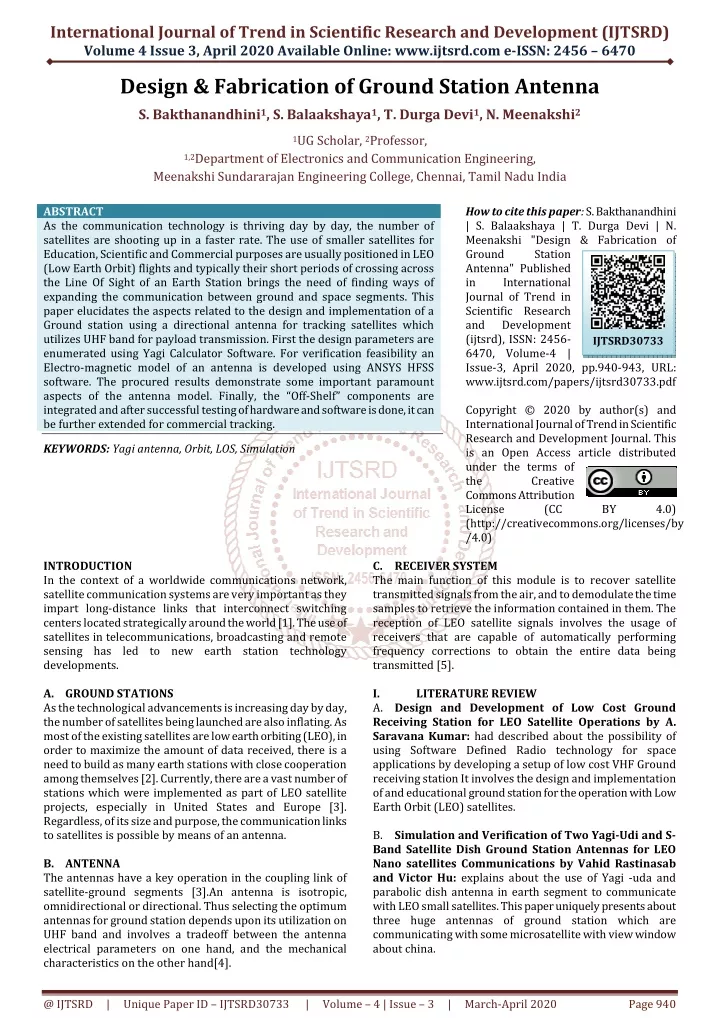
International Journal of Trend in Scientific Research and Development (IJTSRD) Volume 4 Issue 3, April 2020 Available Online: www.ijtsrd.com e-ISSN: 2456 – 6470 Design & Fabrication of Ground Station Antenna S. Bakthanandhini1, S. Balaakshaya1, T. Durga Devi1, N. Meenakshi2 1UG Scholar, 2Professor, 1,2Department of Electronics and Communication Engineering, Meenakshi Sundararajan Engineering College, Chennai, Tamil Nadu India ABSTRACT As the communication technology is thriving day by day, the number of satellites are shooting up in a faster rate. The use of smaller satellites for Education, Scientific and Commercial purposes are usually positioned in LEO (Low Earth Orbit) flights and typically their short periods of crossing across the Line Of Sight of an Earth Station brings the need of finding ways of expanding the communication between ground and space segments. This paper elucidates the aspects related to the design and implementation of a Ground station using a directional antenna for tracking satellites which utilizes UHF band for payload transmission. First the design parameters are enumerated using Yagi Calculator Software. For verification feasibility an Electro-magnetic model of an antenna is developed using ANSYS HFSS software. The procured results demonstrate some important paramount aspects of the antenna model. Finally, the “Off-Shelf” components are integrated and after successful testing of hardware and software is done, it can be further extended for commercial tracking. KEYWORDS: Yagi antenna, Orbit, LOS, Simulation INTRODUCTION In the context of a worldwide communications network, satellite communication systems are very important as they impart long-distance links that interconnect switching centers located strategically around the world [1]. The use of satellites in telecommunications, broadcasting and remote sensing has led to new earth station technology developments. A.GROUND STATIONS As the technological advancements is increasing day by day, the number of satellites being launched are also inflating. As most of the existing satellites are low earth orbiting (LEO), in order to maximize the amount of data received, there is a need to build as many earth stations with close cooperation among themselves [2]. Currently, there are a vast number of stations which were implemented as part of LEO satellite projects, especially in United States and Europe [3]. Regardless, of its size and purpose, the communication links to satellites is possible by means of an antenna. B.ANTENNA The antennas have a key operation in the coupling link of satellite-ground segments [3].An antenna is isotropic, omnidirectional or directional. Thus selecting the optimum antennas for ground station depends upon its utilization on UHF band and involves a tradeoff between the antenna electrical parameters on one hand, and the mechanical characteristics on the other hand[4]. How to cite this paper: S. Bakthanandhini | S. Balaakshaya | T. Durga Devi | N. Meenakshi "Design & Fabrication of Ground Station Antenna" Published in International Journal of Trend in Scientific Research and Development (ijtsrd), ISSN: 2456- 6470, Volume-4 | Issue-3, April 2020, pp.940-943, URL: www.ijtsrd.com/papers/ijtsrd30733.pdf Copyright © 2020 by author(s) and International Journal of Trend in Scientific Research and Development Journal. This is an Open Access article distributed under the terms of the Creative Commons Attribution License (CC (http://creativecommons.org/licenses/by /4.0) C.RECEIVER SYSTEM The main function of this module is to recover satellite transmitted signals from the air, and to demodulate the time samples to retrieve the information contained in them. The reception of LEO satellite signals involves the usage of receivers that are capable of automatically performing frequency corrections to obtain the entire data being transmitted [5]. I. LITERATURE REVIEW A.Design and Development of Low Cost Ground Receiving Station for LEO Satellite Operations by A. Saravana Kumar: had described about the possibility of using Software Defined Radio technology for space applications by developing a setup of low cost VHF Ground receiving station It involves the design and implementation of and educational ground station for the operation with Low Earth Orbit (LEO) satellites. B.Simulation and Verification of Two Yagi-Udi and S- Band Satellite Dish Ground Station Antennas for LEO Nano satellites Communications by Vahid Rastinasab and Victor Hu: explains about the use of Yagi -uda and parabolic dish antenna in earth segment to communicate with LEO small satellites. This paper uniquely presents about three huge antennas of ground station which are communicating with some microsatellite with view window about china. IJTSRD30733 BY 4.0) @ IJTSRD | Unique Paper ID – IJTSRD30733 | Volume – 4 | Issue – 3 | March-April 2020 Page 940
International Journal of Trend in Scientific Research and Development (IJTSRD) @ www.ijtsrd.com eISSN: 2456-6470 C. Design and Performance Evaluation of Two Unit Yagi Uda Array for UHF satellite Communication by Rupesh Lad: exclaims the use of Cube satellite which restricts the total available solar power that can be harnessed, as a result radio links operate on stringent power budget This paper describes the electrical simulation of circularly polarized crossed Yagi antenna using 4NEC2 software. C.Design of a Yagi-Uda Antenna for the Ground tracking station and analysis of Experimental Pay Loads for university Sponsored nanosatellite program by Pawan Kumar Nanduri: had explained about the design of Ground station for a Nano satellite (LEO) and boils down to the design process. It takes a Novel approach and explains the reason in picking this antenna and specification parameter involved in designing. Simulation is being done using: Antenna Maker software, 4NEC2 Software. II. GROUND STATION ARCHITECTURE AND HARD - WARE IMPLEMENTATION The ground station has been constructed to serve as the primary downlink facility to track and collect data from the team’s satellite. Apart from tracking its own satellite, the ground station is also capable of automatically tracking any other satellite as and when the need arises. A.BLOCK DIAGRAM A Ground station basically consist of an antenna and a receiver connected to a power supply along with the data peripheral to observe and collect the data. RTL SDR The Register Transfer Level Software Defined Radio receiver consists of components such as mixer, amplifier, filter, modulator, demodulator, A/D converters implemented by means of software on PC or Embedded system. The SDR Dongle which we used is shown in figure. Softwares like Seeder and SDRSHARP can be used to receive and decode data. DESIGN PROCESS OF 7 ELEMENT YAGI-UDA ANTENNA DESIGN CONSIDERATION: The dimensions of the element are frequency dependent.λ be the wavelength,C be the velocity of light propagation in air 3*10^8,F be the design frequency which is around 47MHz Here λ=c/f=3*10^8/437MHz. EMENT Length of the Driven Element 0.458λ to 0.5λ Length of the reflector Length of the Director1 Length of Director2 Length of Director 3 Spacing between Directors Reflector to Dipole Spacing Dipole to Director Spacing III. SIMULATION SOFTWARE ANSYS HFSS Many simulation softwares are available to obtain the antenna parameters like SWR, Radiation Pattern, Impedance, Gain etc…. Analysis System (ANSYS) HFSS Software can be used for simulation analysis of antenna. HFSS stands for High Frequency Structure Simulator, electromagnetic (EM) simulation software for designing and simulating high-frequency electronic products such as antenna arrays, RF and Microwave components. In HFSS, driven model solution type is used and it uses FEM (Finite Element Method) technique. The antenna designed using Yagi Calculator is simulated and the expected result is shown in figure SPECIFICATION 0.55λ to 0.58λ 0.45λ 0.40λ 0.35λ 0.2λ 0.35λ 0.125λ B.DIRECTIONAL ANTENNA: A Yagi uda array commonly known as Yagi antenna consists of a reflector, number of directors which enhance radiation in one direction when properly arranged on a supporting structure. This directional antenna system consists of array of dipoles and additional closely coupled parasitic elements: 1 reflector, 5 directors, and 1 driven element. which is a 3D Boom is an important part of an antenna support assembly but it also an unintended radiating part of antenna. The driven element is typically a folded dipole and that is directly excited-electrically connected to the feedline.[11] @ IJTSRD | Unique Paper ID – IJTSRD30733 | Volume – 4 | Issue – 3 | March-April 2020 Page 941
International Journal of Trend in Scientific Research and Development (IJTSRD) @ www.ijtsrd.com eISSN: 2456-6470 Figure SWAYAM SATELLITE: Position of swayam satellite ifrom n2yo.com TWO LINE ELEMENT SET; 1 41607U 16040J 20036.44311813 .00001302 00000-0 56795-4 0 9997 2 41607 97.3369 98.8490 0011709 299.1583 60.8482 15.23864013201161 TWO LINE ELEMENT (TLE) SET We can also manually calculate and predict the pass of the satellite over a location using TLE method. A two-line element set is a date format, encoding a list of orbital elements of an Earth-orbiting object for a given point in time, the epoch. Using suitable prediction formula, the state at any point in the past or future can be estimated to some accuracy. IV. There are a diverse varieties of softwares available for satellite tracking such as Orbitron, GPredict, N2YO and Wintrak. By using these softwares we can track the position of satellite and also predict the time of future passes of satellites over the Line Of sight (LOS) of an antenna. N2YO The N2YO site provides real time tracking and pass predictions with orbital paths and footprints overlaid on Google maps. It features an alerting system that automatically notifies user via SMS or email before International Space Station crosses the local sky. The Data obtained from the website for SWAYAM satellite on Feb 6, 2020 is shown in figure Details from n2yo.com for swayam satellite NORAD ID : 41607 SATELLITE TRACKING SOFTWARE INT’L CODE : 2016-040J PERIGEE : 493.3 Km APOGEE : 509.4 km INCLINATION : 97.3 deg PERIOD : 94.5 minutes V. SDRSHARP There are many RTLSDR software’s like SDR#, HSDR, GQRX etc., among these software SDR# is the best software and it is available as free. SDR# is a simple, intuitive, small and fast PC-based DSP application for Software Defined Radio. It’s written in C#.he decoding techniques used in SDR# are AM, NFM, WFM and CW. VI. CONCLUSION AND FUTURE WORK This ground station segment can be further developed by implementing automatic tracking using rotor and rotor controller. WispDDE is a windows application that can be used to interface prediction software to rotor controller. We need both prediction software and WispDDE to run on the same PC simultaneously and have to setup a link between SEMI MAJOR AXIS : 6872 km DECODING OF DATA RCS : unknown LAUNCH DATE : June 22, 2016 SOURCE : India LAUNCH SITE : Sriharikota @ IJTSRD | Unique Paper ID – IJTSRD30733 | Volume – 4 | Issue – 3 | March-April 2020 Page 942
International Journal of Trend in Scientific Research and Development (IJTSRD) @ www.ijtsrd.com eISSN: 2456-6470 [7]Jyh-Ching, T. Chi-Teng, M. Jiun-Jinh, “A Software- Defined Radio Approach For The Implementation Of Ground Station Receivers”, Small Satellite for Earth Observations-Selected Contributions, pp.293-296, ISBN 978-1-4020-6942-0,2008. them. So, by this method we can reduce the human error and also track the satellites for more time automatically. REFERENCES [1]http://azharpaperpresentation.blockspot.com/2010/0 4/satellite-communication.html [8]Ham Radio Science (2013, May 22), Software Defined radio Resources, www.hamradioscience.com/resources/. [2]Adrian done, Alin Mihai Cailean, Cezar-Eduard Lesanu, Mihai Dimian, Adrian Graur, ”Considerations On Ground station Antennas For Communication With LEO Satellites”, [Online]. Available: [9]Lipika Garg, Atharva Kand,”Automated Ground Station Design for an Amateur LEO Satellite System”, 2019 IEEE. [3][5], [6]. J. E. Oros, J. Trejo, A. Salcedo, “Identification, Location and Reception of Low Earth Orbit Satellites Signals”, 2015 International Mechatronics, Electronics and Automotive Engineering (ICMEAE), Prague, 2015, pp.246-250. [10]“Design and Development of Low Cost Ground Receiving Station for LEO Satellite Operations”, Conference on [11]Vahid Rastinasab and Victor Hu”Simulation and verification Two Yagi-Udi and S-band Satellite dish Ground Station Antenna for Leo Nano Satellite Communications”2019 Wireless and Mobile Networks(IJWMN) [4]Allan C. Schell, “Ground-Based Antennas for Satellite Communications” ICSSC, Washington, May 1966J, vol.19, pp. 465-480. Clerk Maxwell, a Treatise on Electricity and Magnetism, 3rd Ed, vol. 2 Oxford: Clarendon, 1892, pp. 68-73. International Journel of [12]”Ground System Design For Receiver-end rf Communication in Amateur Band”2017IEEE. @ IJTSRD | Unique Paper ID – IJTSRD30733 | Volume – 4 | Issue – 3 | March-April 2020 Page 943