Download
1 / 5
50 likes | 56 Views
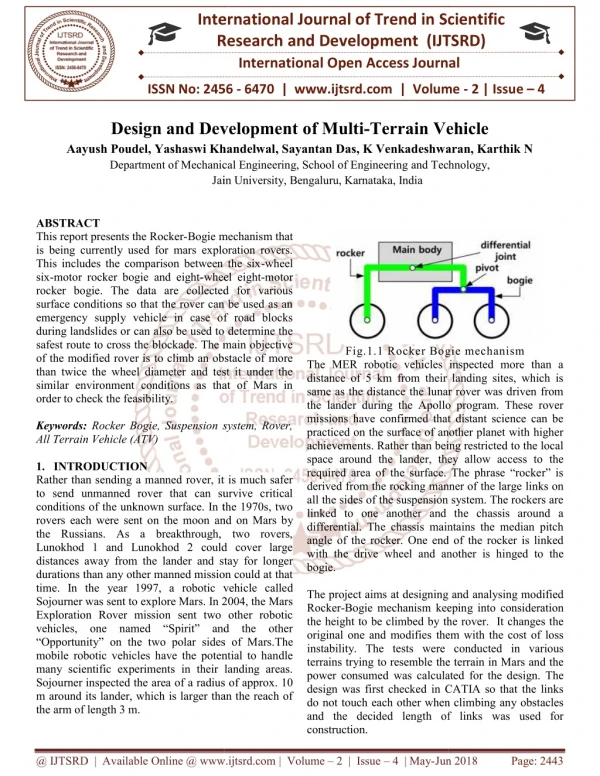
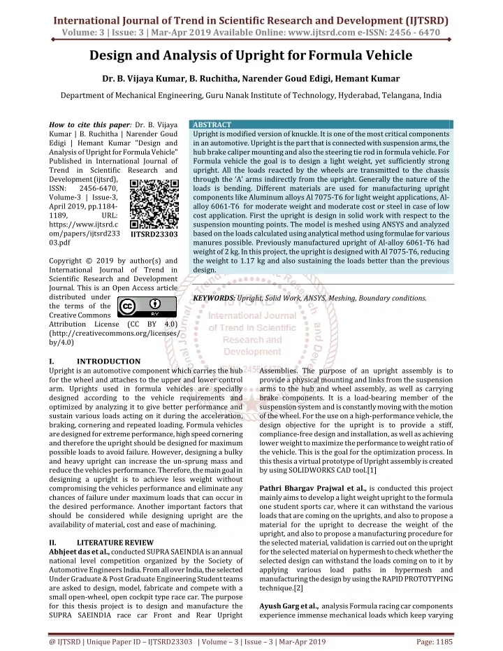
Upright is modified version of knuckle. It is one of the most critical components in an automotive. Upright is the part that is connected with suspension arms, the hub brake caliper mounting and also the steering tie rod in formula vehicle. For Formula vehicle the goal is to design a light weight, yet sufficiently strong upright. All the loads reacted by the wheels are transmitted to the chassis through the 'A' arms indirectly from the upright. Generally the nature of the loads is bending. Different materials are used for manufacturing upright components like Aluminum alloys Al 7075 T6 for light weight applications, Al alloy 6061 T6 for moderate weight and moderate cost or steel in case of low cost application. First the upright is design in solid work with respect to the suspension mounting points. The model is meshed using ANSYS and analyzed based on the loads calculated using analytical method using formulae for various manures possible. Previously manufactured upright of Al alloy 6061 T6 had weight of 2 kg. In this project, the upright is designed with Al 7075 T6, reducing the weight to 1.17 kg and also sustaining the loads better than the previous design. Dr. B. Vijaya Kumar | B. Ruchitha | Narender Goud Edigi | Hemant Kumar "Design and Analysis of Upright for Formula Vehicle" Published in International Journal of Trend in Scientific Research and Development (ijtsrd), ISSN: 2456-6470, Volume-3 | Issue-3 , April 2019, URL: https://www.ijtsrd.com/papers/ijtsrd23303.pdf Paper URL: https://www.ijtsrd.com/engineering/mechanical-engineering/23303/design-and-analysis-of-upright-for-formula-vehicle/dr-b-vijaya-kumar<br>

E N D
International Journal of Trend in Scientific Research and Development (IJTSRD) Volume: 3 | Issue: 3 | Mar-Apr 2019 Available Online: www.ijtsrd.com e-ISSN: 2456 - 6470 Design and Analysis of Upright forFormula Vehicle Dr. B. Vijaya Kumar, B. Ruchitha, Narender Goud Edigi, Hemant Kumar Department of Mechanical Engineering, Guru Nanak Institute of Technology, Hyderabad, Telangana, India How to cite this paper: Dr. B. Vijaya Kumar | B. Ruchitha | Narender Goud Edigi | Hemant Kumar "Design and Analysis of Upright for Formula Vehicle" Published in International Journal of Trend in Scientific Research and Development (ijtsrd), ISSN: 2456-6470, Volume-3 | Issue-3, April 2019, pp.1184- 1189, URL: https://www.ijtsrd.c om/papers/ijtsrd233 03.pdf Copyright © 2019 by author(s) and International Journal of Trend in Scientific Research and Development Journal. This is an Open Access article distributed under the terms of the Creative Commons Attribution License (CC BY 4.0) (http://creativecommons.org/licenses/ by/4.0) I. INTRODUCTION Upright is an automotive component which carries the hub for the wheel and attaches to the upper and lower control arm. Uprights used in formula vehicles are specially designed according to the vehicle requirements and optimized by analyzing it to give better performance and sustain various loads acting on it during the acceleration, braking, cornering and repeated loading. Formula vehicles are designed for extreme performance, high speed cornering and therefore the upright should be designed for maximum possible loads to avoid failure. However, designing a bulky and heavy upright can increase the un-sprung mass and reduce the vehicles performance. Therefore, the main goal in designing a upright is to achieve less weight without compromising the vehicles performance and eliminate any chances of failure under maximum loads that can occur in the desired performance. Another important factors that should be considered while designing upright are the availability of material, cost and ease of machining. II. LITERATURE REVIEW Abhjeet das et al., conducted SUPRA SAEINDIA is an annual national level competition organized by the Society of Automotive Engineers India. From all over India, the selected Under Graduate & Post Graduate Engineering Student teams are asked to design, model, fabricate and compete with a small open-wheel, open cockpit type race car. The purpose for this thesis project is to design and manufacture the SUPRA SAEINDIA race car Front and Rear Upright ABSTRACT Upright is modified version of knuckle. It is one of the most critical components in an automotive. Upright is the part that is connected with suspension arms, the hub brake caliper mounting and also the steering tie rod in formula vehicle. For Formula vehicle the goal is to design a light weight, yet sufficiently strong upright. All the loads reacted by the wheels are transmitted to the chassis through the ‘A’ arms indirectly from the upright. Generally the nature of the loads is bending. Different materials are used for manufacturing upright components like Aluminum alloys Al 7075-T6 for light weight applications, Al- alloy 6061-T6 for moderate weight and moderate cost or steel in case of low cost application. First the upright is design in solid work with respect to the suspension mounting points. The model is meshed using ANSYS and analyzed based on the loads calculated using analytical method using formulae for various manures possible. Previously manufactured upright of Al-alloy 6061-T6 had weight of 2 kg. In this project, the upright is designed with Al 7075-T6, reducing the weight to 1.17 kg and also sustaining the loads better than the previous design. KEYWORDS: Upright, Solid Work, ANSYS, Meshing, Boundary conditions. IJTSRD23303 Assemblies. The purpose of an upright assembly is to provide a physical mounting and links from the suspension arms to the hub and wheel assembly, as well as carrying brake components. It is a load-bearing member of the suspension system and is constantly moving with the motion of the wheel. For the use on a high-performance vehicle, the design objective for the upright is to provide a stiff, compliance-free design and installation, as well as achieving lower weight to maximize the performance to weight ratio of the vehicle. This is the goal for the optimization process. In this thesis a virtual prototype of Upright assembly is created by using SOLIDWORKS CAD tool.[1] Pathri Bhargav Prajwalet al., is conductedthis project mainly aims to develop a light weight upright to the formula one student sports car, where it can withstand the various loads that are coming on the uprights, and also to propose a material for the upright to decrease the weight of the upright, and also to propose a manufacturing procedure for the selected material, validation is carried out on the upright for the selected material on hypermesh to check whether the selected design can withstand the loads coming on to it by applying various load paths manufacturing the design by using the RAPID PROTOTYPING technique.[2] Ayush Garg et al., analysisFormula racing car components experience immense mechanical loads which keep varying in hypermesh and @ IJTSRD | Unique Paper ID – IJTSRD23303 | Volume – 3 | Issue – 3 | Mar-Apr 2019 Page: 1185
International Journal of Trend in Scientific Research and Development (IJTSRD) @ www.ijtsrd.com eISSN: 2456-6470 all through the life span of the components. It is essential to know the life of a component and replace it in time to ensure performance, reliability and durability of the vehicle. This paper addresses the fatigue life analysis of the Uprights for a Formula SAE vehicle and optimization of the design based on the results to increase the life. The front and rear uprights have been designed using the 3D modelling software CATIA and in accordance to the formula SAE rulebook 2018. The analysis parameters are derived from the logics and simulations of the vehicle design parameters using Optimum Dynamics[3]. Pathri Bhargav Prajwal et al., the weight optimisation of the upright is done and its weight is reduced up to 5%, and also the stress concentration is reduced up to 15%, these are the conclusion that has been drawn after the performing analysis as well as optimisation the following are the results that are been drawn, the material that is been chosen for the uprights is aluminium. The weight of the upright that have been supplied to me was 659 grams, the stresses developed in the upright initial and final results are stated below:- Initial stresses in the component for load case -1 = 330MPa Initial stresses in the component for load case- 2 = 333MPa After the optimisation it is surprisingly seen that the stresses are drastically reduced as shown below Final stresses in the component for load case -1 = 281 MPa Final stresses in the component for load case- 2 = 315 MPa Therefore, when compare to initial and final in the load case – 1 there is an decrease in stress value of 14.8% For the load case-2 there is a decrease in stress value of 5.4% In case of the weight there is an overall weight reduction of 6%[4]. Shubham Kumar Verma et al., conventionally used uprights are made of cast-iron, which has more weight for required strength or FOS but by analyzing the upright using Al 6061-T6, we can conclude that our upright is light weighted along with the required strength and parameters. It makes the vehicle to perform well in rough terrain. Umesh S. Sangle et al., the purpose of this paper is not only to design and manufacture the upright assemblies for the car, but also to provide an in-depth study in the process taken to arrive at the final design. With all the project work presented above it can be concluded that the project work has been successfully completed along with completion of all the objectives. In today’s era mass or weight reduction is becoming a core highlighted issue in automobile manufacturing industry to improve fuel efficiency thereby reducing emissions. Weight reduction has been achieved through advances in materials, improved design and analysis methods, fabrication processes and optimization techniques, etc .[5] M Azmeer et al., shape optimization had been performed and the mass of the upright was reduced by 21%. Maximum stress and deformation are within control. The shape optimization gives small change in deformation when several loads are applied, which means that change of volume and shapes does not influence significantly to stiffness of the structure. Therefore, the total weight of the vehicle has been reduced, as well as, costs and materials used. This will improve the fuel efficiency, handling and carbon emission .[6] Rohit B Pawar1 et al., adding composite material on the stainless steel (carbon fibre Kevlar), result is increasing the stress capacity of wheel hub model. Also increase the one- mises stress & shear stress of wheel hub model. Reduce upspring mass by using or adding composite material for manufacturing the wheel hub .[7] III. SOLIDWORKS MODEL Figure 1: Previous upright Figure 2: Newly modified upright IV. PREVIOUS RESULTS Figure 3: Weight of previous upright Material T6 - 6061 T6 Mass - 2023grams Volume - 749257.47cubic millimeters Surface Area - 103462.92square millimeters Center of mass - (millimeters) X=1738.75 Y=583.21 Z=309.37 @ IJTSRD | Unique Paper ID - IJTSRD23303 | Volume – 3 | Issue – 3 | Mar-Apr 2019 Page: 1186
International Journal of Trend in Scientific Research and Development (IJTSRD) @ www.ijtsrd.com eISSN: 2456-6470 Material Mass(optimized)-1169.19grams Volume Surface Area Center of Mass (millimeters) X= -10.55 Y= -2.43 Z= 23.99 CENTRIFUGAL FORCE: It is the force acting towards the centre of the turn. The figure below Fig. 7 shows the fixed supports in analysing centrifugal stresses. -7075T6 -416080.69cubic millimeters -103236.17square millimeters Figure 4 : Total deformation Figure 5: Equivalent Stress Total Force =10000N V. CALCULATIONS Updated individual forces calculations of Upright Longitudinal force: Assume: vehicle weight with driver = 280 kg Driver weight = 60 kg Tire weight = 80 kg Force at one side = mass at the rear side of the vehicle x Acceleration Acceleration = ( Vf – Vi ) / time = (3600- 0)/60 = 60 m/s 160 x 0.60 = 110 x 9.81 = 1060 N Lateral Force: Lateral force = weight x g = 180 x 10 = 1800 N Centrifugal Force: Force = mV2/ r V = distance / time = 30 x 5/18 = 8.33 (180 x 8.332) / 6 = 2082 N Assumptions in initially: Speed = 30 kmph Turning radius = 6 m Forces on calliper mountings or Torque: T = Torque / radius = ( 503 x 0.5 )/ 2 = 125.75 N-mm2 Lateral shear failure of the Upright Bracket = 125.75 N/mm2 FOS = 1 will support only design load and no more. Any additional load will cause the structure to fail. A structure with a FOS of 2 will fail at twice the design load VI. RESULTS AND DISCUSSION OF MODIFIED UPRIGHT Figure 7: Fixed Support of Centrifugal force on upright Figure 6 Equivalent stress due to Centrifugal force Figure8: Total Deformation due to Centrifugal force Figure 6: Weight of Modified Upright Figure 9: Total strain due to Centrifugal force @ IJTSRD | Unique Paper ID - IJTSRD23303 | Volume – 3 | Issue – 3 | Mar-Apr 2019 Page: 1187
International Journal of Trend in Scientific Research and Development (IJTSRD) @ www.ijtsrd.com eISSN: 2456-6470 In the centrifugal force analysis, shown in fig. 8, we got equivalent stress of maximum at 5.036 MPa and minimum of 3.19 MPa and total deformation shown in fig.8 max. 0.0522 mm and min. 0 and total strain shown in fig. 9, max. 8.22e and min. 2.2945e. LATERAL FORCE: These are the forces acting on upright in lateral or sideward direction. The fixed points for this analysis is shown in figure 10. Figure 14:Fixed support of longitudinal force on upright Figure 10: Fixed support of lateral force on upright Figure 15: Equivalent Total Strain due to longitudinal forces Figure 11: Equivalent Stress due to lateral forces Figure 16: Equivalent stress due to longitudinal forces Figure 12: Equivalent total strain due to lateral forces Figure 17: Equivalent Total deformation due to longitudinal forces In the longitudinal analysis, shown in fig.15 we got equivalent strain 3.51e max. and min. 1.59e. Equivalent stress shown in fig. 16, max. of 85.2 MPa and 6.42e MPa. Total deformation, shown in fig. 17, max. of 0.00055mm and min. 0mm. TORQUE FORCES: Torque is twisting force. It is a measurement of the force available to turn a shaft or an axle under resistance. The fixed supports for analysis are shown in blue in the fig. 18 Figure 13: Total Deformation due to lateral forces In this lateral analysis, as shown in fig. 11 we got equivalent stress max. 7.4 MPa min. 0 MPa and equivalent strain, as shown in fig. 12 max. strain 3.72e and min. 2.37e and total deformation max. 0.00184 and min. 0 mm. LONGITUDINAL FORCES: These are the forces that act in horizontal direction to the upright. The fixed supports for analysis are shown in blue in the figure 14. @ IJTSRD | Unique Paper ID - IJTSRD23303 | Volume – 3 | Issue – 3 | Mar-Apr 2019 Page: 1188
International Journal of Trend in Scientific Research and Development (IJTSRD) @ www.ijtsrd.com eISSN: 2456-6470 VI. The modified design of upright is formed by analysing of the previous design of upright and optimising its design. It has less weight (1.17 kg) compared to the previous design of upright weight (2 kg). The strength of upright is retained and its flexibility to adjust to the requirements of vehicle design is also increased. The factor of safety of 2 is maintained for the design. VII. REFERENCES [1] Abhijeet Das- International Journal of Mechanical and Industrial Technology, Vol. 2, Issue 2, pp: (79- 86). CONCLUSION Figure 18: Fixed support of torque on upright [2] Pathri Bhargav Prajwal-Design Optimization of Formula One Student Sports Car Upright Using hypermesh. Mechanical Dehradun Institute of Technology, Dehradun Engineering Deptt, [3] Ayush Garg-International Journal of Science and Research (IJSR), 2015. [4] Design Optimization of Formula One Student Sports Car Upright Using Hyper mesh, Pathri Bhargav Prajwal, International Journal of Mechanical and Industrial Engineering (IJMIE), Vol-2, Issue-1, 2012 Figure 19: Torque Total strain [5] Design & fabrication of Front Wheel Upright Assembly for an ATV, Umesh S. Sangle, International Research Journal of Engineering and Technology (IRJET) Volume: 05 Issue: 04 Apr-2018. [6] Design optimization of rear uprights for UniMAP Automotive Racing Team Formula SAE racing car, M Azmeer1, M H Basha, M F Hamid, M T a Rahman and M S M Hashim, Journal of Physics: Conf. Series 908 (2017). [7] Kunal garde- International Journal of Engineering Research and Development, Volume 10, Issue 10 (October 2014), PP.65-69. Figure 20: Torque Total Deformation [8] Sameer Santosh Mahadik- Mechanical Engineering Department, G.V. Acharya Institute of Engineering and Technology, Shelu Road, Shelu, Maharashtra – 410101, India. Received 18 Feb 2018, Accepted 20 April 2018, Available online 26 April 2018, Vol.8, No.2 [9] Simulation and Optimization of wheel Hub and Upright of Vehicle: A Review Gaurav Saxena, Ankit Singh Chauhan, Rohit Jain and Ishwar Gupta, Journal of Mechanical and Civil Engineering 14, Issue 1 Ver. III (Jan. - Feb. 2017), PP 42-50. Figure 21: Torque equivalent stress In the torque analysis, shown in fig. 19, we got equivalent strain max. 3.51 and min. 1.59 . Equivalent stress shown in fig. 21, max. 0.016 MPa and min. 4.58e MPa. Total deformation , shown in fig. 21, max. 6.8 mm and min. 0mm. ASSEMBLY OF UPRIGHT COMPONENTS [10] Design and analysis of upright in All Terrain Vehicles Shubham Kumar Verma, Amit Kumar Sinha and Ankush Anand, International Journal of Advance Research and Innovation Volume 5 Issue 3 (2017) 341-342 Figure 22: Assembly of Upright @ IJTSRD | Unique Paper ID - IJTSRD23303 | Volume – 3 | Issue – 3 | Mar-Apr 2019 Page: 1189