Download
1 / 7
70 likes | 82 Views
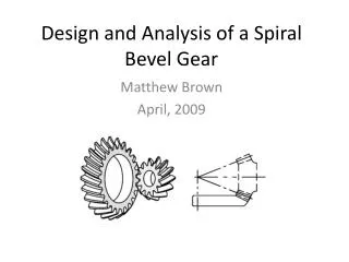
Gear is a power transmitting element among the rotating shafts by means of progressive meeting of projections which is identified as teeth. The purpose of the gear is transmitting torque power among rotating shafts when the central distance between the shafts is comparatively less. The main aim of the paper is to Design and Analysis of a helical gear for marine applications, by using empirical formulas and Calculation, from the data to draw a 3D model helical gear by using Pro Engineer Software and the Structural and Thermal Analysis is done by the Simulation Software ANSYS . Structural and thermal analysis is done using two materials Nickel Chromium Molybdenum Alloy Steel and Aluminum Alloy A360. Structural analysis and thermal analysis is done to conform to the Displacement, Von Mises Stress, and thermal properties related nodal temperature, thermal gradient and thermal flux. Koodali Srinivasarao | A. Sirisha Bhadrakali "Design and Analysis of Helical Gear with different Materials by using Pro/E and Ansys" Published in International Journal of Trend in Scientific Research and Development (ijtsrd), ISSN: 2456-6470, Volume-2 | Issue-2 , February 2018, URL: https://www.ijtsrd.com/papers/ijtsrd10723.pdf Paper URL: http://www.ijtsrd.com/engineering/mechanical-engineering/10723/design-and-analysis-of-helical-gear-with-different-materials-by-using-proe-and-ansys/koodali-srinivasarao<br>

E N D
International Research Research and Development (IJTSRD) International Open Access Journal of Helical Gear with different Materials by using Pro/E and Ansys International Journal of Trend in Scientific Scientific (IJTSRD) International Open Access Journal ISSN No: 2456 ISSN No: 2456 - 6470 | www.ijtsrd.com | Volume www.ijtsrd.com | Volume - 2 | Issue – 2 Design and Analysis of Helical Gear with different Materials by using of Helical Gear with different Materials by using Koodali Srinivasarao M.Tech Student,Department of Mechanical Engineering, Aditya Engineering College Surampalem, Andhra Pradesh, India A. Sirisha Bhadrakali A. Sirisha Bhadrakali Department of Mechanical Aditya Engineering College Surampalem, Andhra Pradesh, India Department of Mechanical Aditya Engineering College Assistant Professor,Department of Mechanical Engineering, Aditya Engineering College Surampalem, Andhra Pradesh , India ABSTRACT Gear is a power transmitting element among the rotating shafts by means of progressive meeting of projections which is identified as teeth. The purpose of the gear is transmitting torque (power) among rotating shafts when the central distance between the shafts is comparatively less. The main aim of the paper is to Design and Analysis of a helical gear for marine applications, by using empirical formulas and Calculation, from the data to draw a 3D model helical gear by using Pro/Engineer Software and the Structural and Thermal Analysis done by the Simulation Software (ANSYS). Structural and thermal analysis is done using two materials Nickel Chromium Molybdenum Alloy Steel and Aluminum Alloy A360. Structural analysis and thermal analysis is done to conform to the Displacement, Von Mises Stress, and thermal properties related nodal temperature, thermal gradient and thermal flux. Keywords: Displacement, Von Mises stress, Thermal Gradient, Thermal Flux, Pro/ E and ANSYS method 1.0INTRODUCTION TO GEARS A gear is a rotating machine element including a cut tooth, or cogs, which mesh with by resources of a further toothed element in order to transmit torque. Two or more gears operational in meshed are termed a transmit and can create a mechanical benefit during a transmit and can create a mechanical benefit during Gear is a power transmitting element among the rotating shafts by means of progressive meeting of projections which is identified as teeth. The purpose of the gear is transmitting torque (power) among rotating shafts when the central distance between the a gear ratio and thus may be measured an uncomplicated machine. Geared can modify the speed, magnitude and direction of a power supply. The common state is meant for a gear to mesh with another gear; still a gear can also mesh a non gear toothed element, known as rack, thus producing linear motion instead of turning round. The gears transmit equivalent to the wheels in a pulley. A benefit of gears is to p means of gear teeth. While two gears of uneven number of teeth are mutual a mechanical gain is formed, with both the rotational speeds and the torques of the two gears opposed in an easy correlations In transmissions which propose ratios, such as bicycles and cars, the term gear, as in first gear, submitted to a gear ratio fairly than a real physical gear. The expression is worn to explain similar devices yet when gear ratio is unbroken slightly than separate, or when device does not really contain any gears, as in as always uneven transmission. The originated orientation to gears was circa 50 A.D. by Hero of Alexandria, but they influenced back to the Greek mechanics of the Alexandrian educate in the 3rd century BC and were deeply residential by the Greek polymath Archimedes (287 Greek polymath Archimedes (287-212 BC). a gear ratio and thus may be measured an uncomplicated machine. Geared can modify the speed, magnitude and direction of a power supply. for a gear to mesh with another gear; still a gear can also mesh a non-rotating gear toothed element, known as rack, thus producing linear motion instead of turning round. The main aim of the paper is to Design and Analysis of a helical gear for marine applications, by using empirical formulas and Calculation, from the data to draw a 3D model helical gear by using Pro/Engineer Software and the Structural and Thermal Analysis is done by the Simulation Software (ANSYS). The gears transmit equivalent to the wheels in a pulley. A benefit of gears is to put off slipping by While two gears of uneven number of teeth are mutual a mechanical gain is formed, with both the rotational speeds and the torques of the two gears opposed in an easy correlations Structural and thermal analysis is done using two materials Nickel Chromium Molybdenum Alloy Steel and Aluminum Alloy A360. Structural analysis and thermal analysis is done to conform to the ses Stress, and thermal properties related nodal temperature, thermal gradient In transmissions which propose multiple gear ratios, such as bicycles and cars, the term gear, as in first gear, submitted to a gear ratio fairly than a real physical gear. The expression is worn to explain similar devices yet when gear ratio is unbroken slightly than separate, or when the device does not really contain any gears, as in as Displacement, Von Mises stress, Thermal Gradient, Thermal Flux, Pro/ E and ANSYS method A gear is a rotating machine element including a cut tooth, or cogs, which mesh with by resources of a further toothed element in order to transmit torque. gears operational in meshed are termed The originated orientation to gears was circa 50 A.D. by Hero of Alexandria, but they influenced back to the Greek mechanics of the Alexandrian educate in C and were deeply residential by the @ IJTSRD | Available Online @ www.ijtsrd.com @ IJTSRD | Available Online @ www.ijtsrd.com | Volume – 2 | Issue – 2 | Jan-Feb 2018 Feb 2018 Page: 1422
International Journal of Trend in Scientific Research and Development (IJTSRD) ISSN: 2456-6470 Thermal simulations play an important role in the design of many engineering applications, including internal combustion engines, exchangers, piping systems, components. In many cases, engineers follow a thermal analysis with a stress analysis to calculate thermal stresses (that is, stresses caused by thermal expansions or contractions). 1.1Thermal Analysis A thermal analysis calculates the temperature distribution and related thermal quantities in a system or component. Typical thermal quantities of interest are: The temperature distributions The amount of heat lost or gained Thermal gradients Thermal fluxes. 2.0MODEL OF HELICAL GEAR turbines, and heat electronic Fig.1.Helical Gear in Pro/E 3.0 STRUCTURAL ANALYSIS OF HELICAL GEAR USING STEEL Fig.2. Von Mises Stress for Steel @ IJTSRD | Available Online @ www.ijtsrd.com | Volume – 2 | Issue – 2 | Jan-Feb 2018 Page: 1423
International Journal of Trend in Scientific Research and Development (IJTSRD) ISSN: 2456-6470 3.1Structural Analysis of Helical Gear Using NiCrM Alloy Steel Fig.3. Von Mises Stress for NiCrM Alloy Steel 3.2 Structural Analysis of Helical Gear Using Aluminum Alloy A360 Fig.4 Von Mises Stress for Aluminum Alloy A360 4.0 THERMAL ANALYSIS OF HELICAL GEAR USING STEEL Fig.5 Thermal flux vector sum for Steel @ IJTSRD | Available Online @ www.ijtsrd.com | Volume – 2 | Issue – 2 | Jan-Feb 2018 Page: 1424
International Journal of Trend in Scientific Research and Development (IJTSRD) ISSN: 2456-6470 4.1 Thermal Analysis of Helical Gear using NiCrM Alloy Steel Fig. 6 Thermal flux vector sum for NiCrM Alloy Steel 4.2 Thermal Analysis of Helical Gear using Aluminum Alloy A360 Fig. 7.Thermal flux vector sum for Aluminum Alloy A360 5.0 RESULTS Displacement(mm) 0.012 0.01 0.008 0.006 0.004 0.002 Displacement (mm) 0 Steel Nickel Chromium Molybdenum Alloy Steel Aluminum Alloy A360 Fig. 8 Displacement for Steel, NiCrM Alloy and Al Alloy A360 @ IJTSRD | Available Online @ www.ijtsrd.com | Volume – 2 | Issue – 2 | Jan-Feb 2018 Page: 1425
International Journal of Trend in Scientific Research and Development (IJTSRD) ISSN: 2456-6470 Von Mises Stress (N/mm2) 115 110 105 100 95 Von Mises Stress (N/mm2) 90 85 Nickel Chromium Molybdnum Alloy Steel Steel Aluminum Alloy A360 Fig. 9.Von Mises Stress for Steel, NiCrM Alloy and Al Alloy A360 Thermal Gradient (K/mm) 1200 1000 800 600 400 200 Thermal Gradient (K/mm) 0 Steel Nickel Chromium Molybdnum Alloy Steel Aluminum Alloy A360 Fig.10. Thermal Gradient for Steel, NiCrM Alloy and Al Alloy A360 Thermal Flux (W/mm2) 190 185 180 175 170 165 160 155 Thermal Flux (W/mm2) 150 Steel Nickel Chromium Molybdnum Alloy Steel Aluminum Alloy A360 Fig.11 Thermal Flux for Steel, NiCrM Alloy @ IJTSRD | Available Online @ www.ijtsrd.com | Volume – 2 | Issue – 2 | Jan-Feb 2018 Page: 1426
International Journal of Trend in Scientific Research and Development (IJTSRD) ISSN: 2456-6470 Displace ment (mm) Von- Mises Stress (N/mm2) Nodal Temperatu re (K) Therml Gradie nt (K/mm ) 800.611 Therma l Flux (W/mm 2) .007581 105.263 373 170.48 Steel 0.003881 110.729 373 387.786 162.87 Nickel Chromium Molybdenu m Alloy Steel Aluminu m Alloy A360 0.010722 96.003 373 1069 186.056 As per analysis images, we have observed that displacement of three materials, Aluminum alloy A360 is more valves are obtained. Then von Mises stress are also compared to these three materials, Aluminum alloy A360 is lower than the steel and NiCrM alloy steel. The thermal gradient and thermal flux are compared with other materials. We have observed Aluminum alloy A360 is more. Then finally we have observed this is safe working condition because of the von-Mises stress valves are obtained from the analysis is less than the yield stress values. 6.0 CONCLUSIONS In our project, we have designed a helical gear used in marine applications using theoretical calculations and modeling of helical gear is done in Pro/Engineer. We have performed Structural analysis and thermal analysis on helical gear using Steel, NiCrM Alloy Steel and Aluminum alloy A360. By observing the analysis results, the stress values obtained are less than their respective yield stresses for three materials. So we can decide that our design is safe under working conditions. By comparing the analysis of the three materials, The thermal Gradient of Aluminum alloy A360 is greater than Steel and Nickel Chromium Molybdenum Alloy Steel The Von Mises Stress of Aluminum alloy A360 is less than Steel and Nickel Chromium Molybdenum Alloy Steel. The thermal Gradientof Aluminum alloy A360is greater than Steel and Nickel Chromium Molybdenum Alloy Steel The thermal flux of Aluminum alloy A360 is more than Steel and Nickel Chromium Molybdenum Alloy Steel. So we can say that using Aluminum alloy A360 for helical gear is more advantageous than using Steel and Nickel Chromium Molybdenum AlloySteel as per our analysis. 7.0 REFERENCES 1)Akinnuli B. O., Ogedengbe T. I. And Oladosu K. O. Published On Computer Aided Design and Drafting of Helical, Journal of Emerging Trends in Engineering and Applied Sciences (JETEAS) 3(6): 959-968, Scholar link Research Institute Journals, 2012 (ISSN: 2141-7016). 2)B. Venkatesh, V. Kamala and A.M.K. Prasad Paper Published On Design, Modelling and Manufacturing of RESEARCH, DINDIGUL, No1, 2010. Helical Gear IJAE @ IJTSRD | Available Online @ www.ijtsrd.com | Volume – 2 | Issue – 2 | Jan-Feb 2018 Page: 1427
International Journal of Trend in Scientific Research and Development (IJTSRD) ISSN: 2456-6470 7)Modi Prashant1 Paper Published On Design and Analysis of Helical Gear Using Ansys, Fem &Agma, International Research Journal of Engineering and Technology (IRJET), e-ISSN: 2395 -0056, Volume: 04 Issue: 01-Jan -2017 3)Vinay Kumar C. Jadhav, Rahulkumar M. Sonarand Santosh D. Sancheti Paper Published On FEA of Titanium Helical Gear Set, International Journal of Modern Trends in Engineering and Research-ISSN No.:2349-9745, Date: 28-30 April, 2016. 8)S. K. Suresh Kumarand S. Navaneethan Paper Published On Contact Stress Analysis of Helical Gear Pairs of Different Helix Angle, International Journal of Advanced Research in, ISSN: 2278- 6252, Engineering and Applied Sciences Impact Factor: 5.795. 4)Chetan E. Kolambe and Dhananjay R. BardePaper Published On Study of Helical Gear Analysis Using FEA Software, DOI 10.4010/2016.517 ISSN 2321 3361, 2016IJESC 5)J. Venkatesh and Mr. P. B. G. S. N. Murthy Paper Published On Design and Structural Analysis of High Speed Helical Gear Using Ansys, Int. Journal of Engineering Applications, ISSN: 2248-9622, Vol. 4, Issue 3(Version 2), March 2014, Pp.01-05 9)Machine Design by R.S. Khurmi 10)Handbook of Gear Design byMaitra Research and 11)Handbook Of Practical Gear Design By Darle W. Dudley 12)Design Of Machine Elements By Bhandari 6)MO hit Singh, Wares Khan and Sanjeev Kumar Paper Published On Structural Analysis of Composite Material Helical Gear Under Different Loading Condition, International Journal of Engineering Sciences & Research Technology, Singh* Et Al.,5. 10.5281/Zenodo.55629. (6): June-2016, Doi: @ IJTSRD | Available Online @ www.ijtsrd.com | Volume – 2 | Issue – 2 | Jan-Feb 2018 Page: 1428