Download
1 / 5
50 likes | 60 Views
"This paper proposes to model a voltage sensor based MPPT with voltage reference control technique with a PI controller for the SEPIC converter. The PI controller will minimize the error between the reference voltage VRef generated by the MPPT controller and the panel voltage VPV . Thus, it is an adaptive solution, as if VPV is far from MPP, error will be large and so it will automatically produce large step size D and vice versa. Thus, the MPPT with voltage reference control technique with the association of PI controller can effectively improve the performance of the PV system. The simulations were performed in the environment of MATLAB SIMULINK. Giri Babu | A. Raja Babu ""Control of Stand Alone PV System using Single Voltage Sensor Based MPPT"" Published in International Journal of Trend in Scientific Research and Development (ijtsrd), ISSN: 2456-6470, Volume-4 | Issue-2 , February 2020, URL: https://www.ijtsrd.com/papers/ijtsrd29810.pdf<br><br>Paper Url : https://www.ijtsrd.com/engineering/electrical-engineering/29810/control-of-stand-alone-pv-system-using-single-voltage-sensor-based-mppt/giri-babu"<br>

E N D
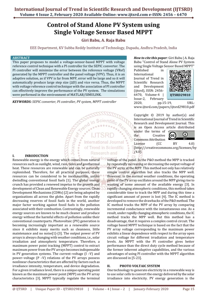
International Journal of Trend in Scientific Research and Development (IJTSRD) Volume 4 Issue 2, February 2020 Available Online: www.ijtsrd.com e-ISSN: 2456 – 6470 Control of Stand Alone PV System using Single Voltage Sensor Based MPPT Giri Babu, A. Raja Babu EEE Department, KV Subba Reddy Institute of Technology, Dupadu, Andhra Pradesh, India ABSTRACT This paper proposes to model a voltage-sensor-based MPPT with voltage reference control technique with a PI controller for the SEPIC converter. The PI controller will minimize the error between the reference voltage (VRef) generated by the MPPT controller and the panel voltage (VPV). Thus, it is an adaptive solution, as if VPV is far from MPP, error will be large and so it will automatically produce large step size (∆D) and vice versa. Thus, the MPPT with voltage reference control technique with the association of PI controller can effectively improve the performance of the PV system. The simulations were performed in the environment of MATLAB/SIMULINK. KEYWORDS: SEPIC converter, PI controller, PV system, MPPT controller How to cite this paper: Giri Babu | A. Raja Babu "Control of Stand Alone PV System using Single Voltage Sensor Based MPPT" Published in International Journal of Trend in Scientific Research and Development (ijtsrd), ISSN: 2456- 6470, Volume-4 | Issue-2, February 2020, pp.15-19, www.ijtsrd.com/papers/ijtsrd29810.pdf Copyright © 2019 by author(s) and International Journal of Trend in Scientific Research and Development Journal. This is an Open Access article distributed under the terms of the Creative Commons Attribution License (CC (http://creativecommons.org/licenses/by /4.0) IJTSRD29810 URL: BY 4.0) I. Renewable energy is the energy which comes from natural resources such as sunlight, wind, rain, tides and geothermal heat. These resources are renewable and can be naturally replenished. Therefore, for all practical purposes, these resources can be considered to be inexhaustible, unlike dwindling conventional fossil fuels [1]. The global energy crunch has provided a renewed impetus to the growth and development of Clean and Renewable Energy sources. Clean Development Mechanisms (CDMs) [2] are being adopted by organizations all across the globe. Apart from the rapidly decreasing reserves of fossil fuels in the world, another major factor working against fossil fuels is the pollution associated with their combustion. Contrastingly, renewable energy sources are known to be much cleaner and produce energy without the harmful effects of pollution unlike their conventional counterparts. Photovoltaic (PV) generation is becoming increasingly important as a renewable source since it exhibits many merits such as cleanness, little maintenance and no noise[1]-[3]. The output power of PV arrays is always changing with weather conditions, i.e., solar irradiation and atmospheric temperature. Therefore, a maximum power point tracking (MPPT) control to extract maximum power from the PV arrays becomes indispensable in PV generation systems. The current–voltage (I –V) and power–voltage (P –V) relations of the PV arrays possess nonlinear characteristics that are affected by factors such as irradiance intensity, temperature, and device degradation. For a given irradiance level, there is a unique operating point known as the maximum power point (MPP) on the PV array characteristics [3]. MPPT typically regulate the terminal INRODUCTION voltage of the panel. In the P&O method the MPP is tracked by repeatedly increasing or decreasing the output voltage of the PV array at the MPP. This method not only has relatively simple control algorithm but also tracks the MPP well. However, in the normal weather conditions, the operating point of the PV array oscillates around the MPP giving rise to wasting of some amount of the available energy [3]. In rapidly changing atmospheric conditions, this method takes considerable time to track the MPP and during this time a significant amount of power is lost [4]. The IC method is developed to remove the drawbacks of the P&O method. The IC method tracks the MPP of the PV array by comparing incremental conductance with the instantaneous one. As a result, under rapidly changing atmospheric conditions, the IC method tracks the MPP well. But this method has a disadvantage, that it requires a complex control circuit. The voltage based MPPT technique is based on the fact that the PV array voltage corresponding to the maximum power exhibits a linear dependence with respect to the array open circuit voltage for different irradiation and temperature levels. An MPPT with the PI controller gives better performance than the direct duty cycle method because of the former inherent adaptive capabilities, and the various advantages of using PI controller with the MPPT algorithm are discussed in [5-23]. II. PHOTO VOLTAIC SYSTEM One technology to generate electricity in a renewable way is to use solar cells to convert the energy delivered by the solar irradiance into electricity. PV energy generation is the @ IJTSRD | Unique Paper ID – IJTSRD29810 | Volume – 4 | Issue – 2 | January-February 2020 Page 15
International Journal of Trend in Scientific Research and Development (IJTSRD) @ www.ijtsrd.com eISSN: 2456-6470 current subject of much commercial and academic interest. Recent work indicates that in the medium to longer term PV generation may become commercially so attractive that there will be large-scale implementation in many parts of the developed world. largest variations in the output power of PV systems. Squall lines can cause the output power of a PV system to fall to zero, and thus, they lead to the worst-case scenario for the operation of the system. However, squall lines are predictable, and thus, the periods of time during which the PV system will be out of service can be predicted. On the other hand, cumulus clouds result in lower loss of the PV power, but they cause the output of the PV system to fluctuate more frequently as the irradiance fluctuates due to the passage of such clouds. The time period of fluctuations can range from few minutes to hours depending on the wind speed, the type and size of passing clouds, and the area covered by and topology of the PV system. Fig.1: Example of stand-alone PV system Standalone systems mainly consist of a PV panel, a battery bank for storage and an inverter for DC to AC conversion [9- 10] shown in Fig. 2.6. It is also possible to couple a PV system with a fossil-fuel general. In this type of system, the generator is used to recharge the PV battery during long periods of cloudy weather. This “Hybrid” system requires much less fuel and maintenance for the generator, while extending battery life. Fig.3: Characteristic of PV Cell The most severe fluctuations in the output power of PV systems usually occur at maximum irradiance level around noon. This period usually coincides with the off-peak loading period of the electric network, and thus, the operating penetration level of the PV system is greatest. The severity of PV power fluctuations on the electric network is governed by several factors, such as: Type of clouds, Penetration level, and size of PV system, Location of the PV system, Topology of the PV system, and Topology of the electric network. Fig. 3 shows the Ipv - Vpv operating characteristic of a solar cell. Three important operating points should be noted on Fig.4. Fig.2: Example of Grid-connected PV system Grid-connected systems show recently very good potential compared to stand-alone ones, as grid-connected users can sell their unused extra electricity to the utility with high prices and still supply their needs at nights from the utility if they have shortage. Photovoltaic (PV) systems convert light energy into electricity. The term photo is from the Greek which mean “light”. “Volt” is named for Alessandro Volta (1745-1827), a Pioneer in the study of electricity. PV is then could literally mean “light-electricity”. Solar irradiance is the radiant power incident per unit area upon a surface. It is usually expressed in w/m2. Radiant power is the rate of flow of electromagnetic energy. Sunlight consists of electromagnetic waves composed of photons at different energies, which travel at constant speed. Solar radiation has a wave like characteristic with the Wavelength proportional to the photon energy (E). Fluctuation of the solar irradiance due to passage of clouds over a PV array is the main reason behind the fluctuation of the output power of PV systems. There are 10 reported cloud patterns, with cumulus clouds (puffy clouds looking like large cotton balls) and squall lines (a solid line of black clouds) causing the Fig.4: PV Cell Operating Point (λ) inversely Fig. 5: Intersection of the Ipv-Vpv characteristic curve and the load characteristic @ IJTSRD | Unique Paper ID – IJTSRD29810 | Volume – 4 | Issue – 2 | January-February 2020 Page 16
International Journal of Trend in Scientific Research and Development (IJTSRD) @ www.ijtsrd.com eISSN: 2456-6470 Under constant irradiance and cell temperature, the operating point of a PV array is determined by the intersection of the Ipv-Vpvcharacteristic and the load characteristic as shown in Fig. 5. Fig. 6 shows that the maximum power output varies almost linearly with the irradiance. Fig. 7 shows that the maximum output power from the array decreases as the temperature increases. are several algorithms to track the MPP and a few common maximum power point tracking algorithms have been reviewed. For optimal operation, the load line must match the PV arrays MPP locus and if the particular load is not using the maximum power, a power conditioner should be used in between the array and the load. Fig.8: Basic MPPT system The major principle of MPPT is to extract the maximum available power from PV module by making them operate at the most efficient voltage (maximum power point). That is to say; MPPT checks output of PV module, compares it to battery voltage then fixes what is the best power that PV module can produce to charge the battery and converts it to the best voltage to get maximum current into battery. It can also supply power to a DC load, which is connected directly to the battery. The SEPIC is derived from boost converter. Its circuit diagram is shown in Fig.9. Fig. 6: Effect of irradiance on the I-V characteristic at constant cell temperature Fig.9: SEPIC converter The single ended primary inductor converter (SEPIC) is a type of DC/DC converter that allows the electrical potential (voltage) at its output to be greater than, less than or equal to that at its input. Fig.7: Effect of temperature on the I-V characteristic at constant irradiance III. MPPT CONTROLLER For maximum power transfer, the load should be matched to the resistance of the PV panel at MPP. Therefore, to operate the PV panels at its MPP, the system should be able to match the load automatically and also change the orientation of the PV panel to track the Sun if possible (Sun tracking is usually left out of most systems due to the high cost of producing the mechanical tracker). A control system that controls the voltage or current to achieve maximum power is needed. This is achieved using a MPPT algorithm to track the maximum power. Tracking of the maximum power point (MPP) of a Photovoltaic (PV) array is usually an essential part of PV Systems. In general, PV generation systems have two major problems; the conversion efficiency of electric power generation is low (in general less than 17%, especially under low irradiation conditions), and the amount of electric power generated by solar arrays changes continuously with weather conditions. Moreover, the solar cell (current – voltage) characteristic is nonlinear and varies with irradiation and temperature. There is a unique point on the I-V or (power – voltage) curve of the solar array called MPP, at which the entire PV system (array, converter, etc…) operates with maximum efficiency and produces its maximum output power. The location of the MPP is not known, but can be located, either through calculation models, or by search algorithms. Therefore MPPT techniques are needed to maintain the PV array’s operating point at its MPP. A controller that tracks the maximum power point locus of the PV array is known as a MPPT controller. There Fig.10: SEPIC converter with an equivalent linear model of PV source The flow chart of proposed voltage MPPT based PV system is presented in Fig.11. Fig.11: Flowchart of voltage sensor based MPPT through VRef control technique @ IJTSRD | Unique Paper ID – IJTSRD29810 | Volume – 4 | Issue – 2 | January-February 2020 Page 17
International Journal of Trend in Scientific Research and Development (IJTSRD) @ www.ijtsrd.com eISSN: 2456-6470 IV. Schematic diagram of a PV system which is used for the Matlab simulation is shown in Fig.12. SIMULATION RESULTS V. The simulated results prove that the implemented algorithm is effectively improving both the dynamic and steady-state tracking performance of the PV system. The MPPT control architecture can be easily implemented with other converter topologies, but the objective function depends on the modulation index of the respective topology. REFERENCES [1]M. A. S. Masoum, H. Dehbonei, and E. F. Fuchs, “Theoretical and experimental analyses of photovoltaic systems with voltage and current based maximum power-point tracking,” IEEE Trans. Energy Convers., vol. 17, no. 4, pp. 514–522, Dec. 2002. CONCLUSIONS Fig.12: PV connected system 20 G=270W/m2 G=480W/m2 PV Module Power (W) 15 [2]T. Noguchi and H. Matsumoto, “Maximum-power-point tracking method of photovoltaic power system using single transducer,” in Proc. IEEE 29th Annu. Conf. Ind. Electron. Soc. (IECON), Nov. 2003, pp. 2350–2355. 10 5 [3]W. Xiao and W. G. Dunford, “A modified adaptive hill climbing MPPT method for photovoltaic power systems,” in Proc. IEEE PESC, Jun. 2004, pp. 1957– 1963. 0 0 5 10 15 20 Time (s) Fig.13: P–V characteristics The P–V characteristics of the simulated PV module for the irradiance conditions are shown in Fig. 13. The tracking waveforms with the proposed method are shown in Fig. 14, and it can be observed that the transient duration has been reduced and is tracking the corresponding MPP with minimum steady-state oscillations. Thus, the tracking performance of the MPPT controller is improved by the voltage reference control technique in association with the designed PI controller. 25 PV Module Voltage (V) [4]M. A. Elgendy, B. Zahawi, and D. J. Atkinson, “Assessment of perturb and observe MPPT algorithm implementation techniques applications,” IEEE Trans. Sustainable Energy, vol. 3, no. 1, pp. 21–33, Jan. 2012. for PV pumping [5] D. Sera, L. Mathe, T. Kerekes, S. V. Spataru, and R. Teodorescu, “On the perturb-and-observe and incremental conductance MPPT methods for PV systems,” IEEE J. Photovolt., vol. 3, no. 3, pp. 1070– 1078, Jul. 2013. [6] K. L. Lian, J. H. Jhang, and I. S. Tian, “A maximum power point tracking method based on perturb-and-observe combined with particle swarm optimization,” IEEE J. Photovolt., vol. 4, no. 2, pp. 626–633, Mar. 2014. 20 15 10 5 [7] M. Killi and S. Samanta, “Modified perturb and observe MPPT algorithm for drift avoidance in photovoltaic systems,” IEEE Trans. Ind. Electron., vol. 62, no. 9, pp. 5549–5559, Sep. 2015. 0 0 0.5 1 1.5 2 2.5 Time (s) (a) Voltage [8] F. Liu, S. Duan, B. Liu, and Y. Kang, “A variable step size inc MPPT method for PV systems,” IEEE Trans. Ind. Electron., vol. 55, no. 7, pp. 2622–2628, Jul. 2008. 16 PV Module Power (W) 14 12 10 [9] M. A. Elgendy, B. Zahawi, and D. J. Atkinson, “Assessment of the incremental conductance maximum power point tracking algorithm,” IEEE Trans. Sustain. Energy, vol. 4, no. 1, pp. 108–117, Jan. 2013. 8 6 4 2 0 0 0.5 1 1.5 2 2.5 [10]Q. Mei, M. Shan, L. Liu, and J. M. Guerrero, “A novel improved variable step-size incremental-resistance MPPT method for PV systems,” IEEE Trans. Ind. Electron., vol. 58, no. 6, pp. 2427–2434, Jun. 2011. Time (s) (b) Power 0.8 [11]T. Esram, J. W. Kimball, P. T. Krein, P. L. Chapman, and P. Midya, “Dynamic maximum power point tracking of photovoltaic arrays using ripple correlation control,” IEEE Trans. Power Electron., vol. 21, no. 5, pp. 1282– 1291, Sep. 2006. 0.6 duty cycle 0.4 0.2 [12] E. Mamarelis, G. Petrone, and G. Spagnuolo, “Design of a sliding mode-controlled SEPIC for PV MPPT applications,” IEEE Trans. Ind. Electron., vol. 61, no. 7, pp. 3387–3398, Jul. 2014. 0 0 0.5 1 1.5 2 2.5 Time (s) (c) Duty cycle Fig.14: Simulated results using MPPT controller @ IJTSRD | Unique Paper ID – IJTSRD29810 | Volume – 4 | Issue – 2 | January-February 2020 Page 18
International Journal of Trend in Scientific Research and Development (IJTSRD) @ www.ijtsrd.com eISSN: 2456-6470 [13]V. Salas, E. Oliás, A. Barrado, and A. Lázaro, “Review of the maximum power point tracking algorithms for stand-alone photovoltaic systems,” Sol. Energy Mater. Sol. Cells, vol. 90, no. 11, pp. 1555–1578, 2006. [22]A. K. Abdelsalam, A. M. Massoud, S. Ahmed, and P. N. Enjeti, “High-performance adaptive perturb and observe MPPT technique for photovoltaic-based microgrids,” IEEE Trans. Power Electron., vol. 26, no. 4, pp. 1010–1021, Apr. 2011. [14]T. Esram and P. L. Chapman, “Comparison of photovoltaic array maximum power point tracking techniques,” IEEE Trans. Energy Convers., vol. 22, no. 2, pp. 439–449, Jun. 2007. [23]M. G. Villalva, T. de Siqueira, and E. Ruppert, “Voltage regulation of photovoltaic arrays: Small-signal analysis and control design,” IET Power Electron., vol. 3, no. 6, pp. 869–880, Nov. 2010. [15]M. A. G. de Brito, L. Galotto, L. P. Sampaio, G. E. de Azevedo e Melo, and C. A. Canesin, “Evaluation of the main MPPT techniques for photovoltaic applications,” IEEE Trans. Ind. Electron., vol. 60, no. 3, pp. 1156–1167, Mar. 2013. [24]Sunil Kumar Mahapatro, 2013, Maximum Power Point Tracking (MPPT) Of Solar Cell Using Buck-Boost Converter, International Journal of Engineering Research & Technology (IJERT) Volume 02, Issue 05 (May 2013) [16]M. Veerachary, T. Senjyu, and K. Uezato, “Voltage-based maximum power point tracking control of PV system,” IEEE Trans. Aerosp. Electron. Syst., vol. 38, no. 1, pp. 262–270, Jan. 2002. [25]G. Siva Gangadhar, K. Meenendranath Reddy, G. Venkata Suresh Babu “Design and Performance Analysis of Fly Back Convert for PV Application”, vol. 2, no. 12, pp. 145-150, Dec 2015 Author’s Details: K. Giri Babu has received B. Tech from Stanley Engineering and Technology. He is pursuing M. Tech from Dr. K. V. Subba Reddy Kurnool. His areas of interest include Power System, Power Electronics and Electrical Machines. A. Raja Babu is an Asst. Professor at KV Subba Technology, Kurnool. He has 10 years of experience in power system and power electronics field. He has published several international and national conferences and journals. He has attended several international and notional workshops. [17]N. Dasgupta, A. Pandey, and A. K. Mukerjee, “Voltage- sensing-based photovoltaic MPPT with improved tracking and drift avoidance capabilities,” Sol. Energy Mater. Sol. Cells, vol. 92, no. 12, pp. 1552–1558, 2008. Stephen College of [18]M. Killi and S. Samanta, “An adaptive voltage-sensor- based MPPT for photovoltaic systems with sepic converter including steady-state and drift analysis,” IEEE Trans. Ind. Electron., vol. 62, no. 12, pp. 7609– 7619, Dec. 2015. Institute of Technology, [19]S. J. Chiang, H.-J. Shieh, and M.-C. Chen, “Modeling and control of PV charger system with SEPIC converter,” IEEE Trans. Ind. Electron., vol. 56, no. 11, pp. 4344– 4353, Nov. 2009. Reddy Institute of [20]L. Piegari and R. Rizzo, “Adaptive perturb and observe algorithm for photovoltaic maximum power point tracking,” IET Renew. Power Gener., vol. 4, no. 4, pp. 317–328, Jul. 2010. [21]S. Kolesnik and A. Kuperman, “On the equivalence of major variable step- size MPPT algorithms,” IEEE J. Photovolt., vol. 6, no. 2, pp. 590–594, Mar. 2016. @ IJTSRD | Unique Paper ID – IJTSRD29810 | Volume – 4 | Issue – 2 | January-February 2020 Page 19